As construction season winds down, I’m trying to reach completion on some of the multitudinous simultaneous subprojects in the HomeBox. Chief among these goals is I want to finish all the utilities in the T.H.R.O.N.E. Room, ideally to the point of being able to actually install that big, beautiful bathtub that I’ve actually had floating around here for like two years now.
You may recall that the tub was a primary subject of a big chart I drew up earlier, representing visually the perennial truism: before anything can be done, something else must first be done. Let’s see how things are going on that chart, starting with the bottom, the things that (miraculously) don’t have preconditions.
- Cold water feed from loft to first floor utility area (where the water heater was going to be) – the design has changed and this is no longer relevant.
- Seal walls – DONE.
- Hot & cold feeds (now from SUL) – complete enough. While not fully plumbed to the water supply, what goes into the T.H.R.O.N.E. Room is DONE.
- Grout tile accent – DONE.
- Corner trim – DONE (including crown molding).
- Bathroom walls finish – DONE.
- Bathroom fresh water supply – DONE.
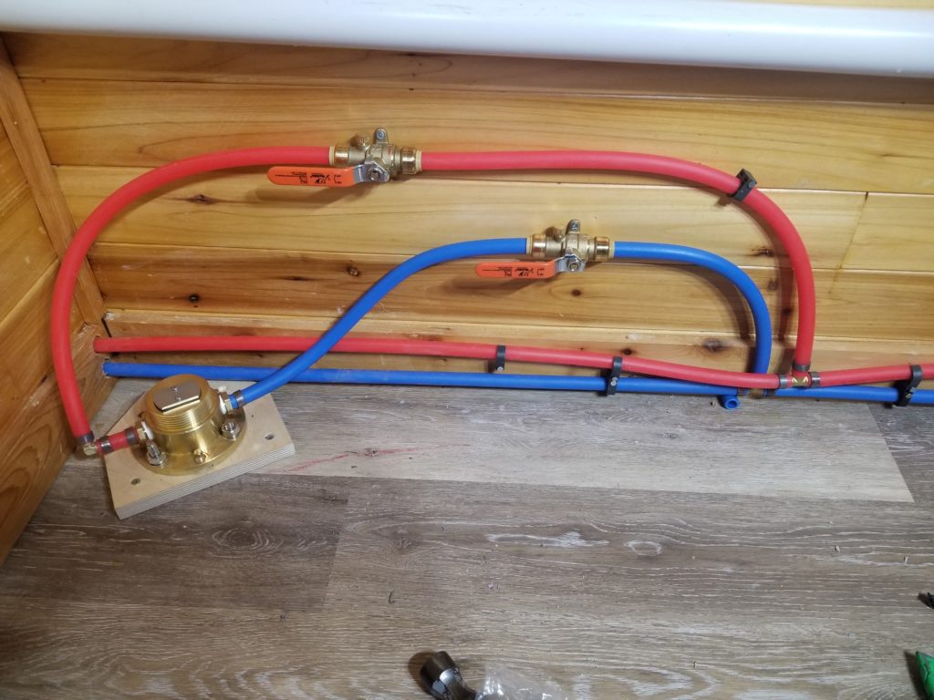
- Wash sink water supply – complete enough. Lines teed off the supply, cutoffs in place but not crimped on, pending final faucet arrangements. The parts that go behind the tub are DONE.
- Bilge chamber & lift pump – very close. Design has changed, this is a single unit now and I need to build an anchor for it before I can hook it all in, but much of that is ready. PENDING.
- Drain from kitchen sink to bilge – DONE. Well, except for one hose clamp, which will be tightened when the bilge pump installation is final.
- Faucet/shower head – design changed; now the tub filler is a freestanding pedestal and the shower is a hand-shower attachment. DONE (pictures below).
- Kitchen drain line – DONE. It doesn’t go to anything, but the part that goes behind the tub is done.
- Gas feed to 1FUA – design changed (did I mention this whole project involved a lot of way-finding?) – gas line now needs to transit the TR and go to the new location for the water heater in the loft. PENDING (parts on hand, ready to do).
- Bilge line to loft – PENDING (parts on hand, ready to do, waiting for other things to be done in a crowded corner).
- Tub drain pump – design changed – no longer needed.
- Tub drain line to bilge pump – planned, not done, will be part of tub final install.
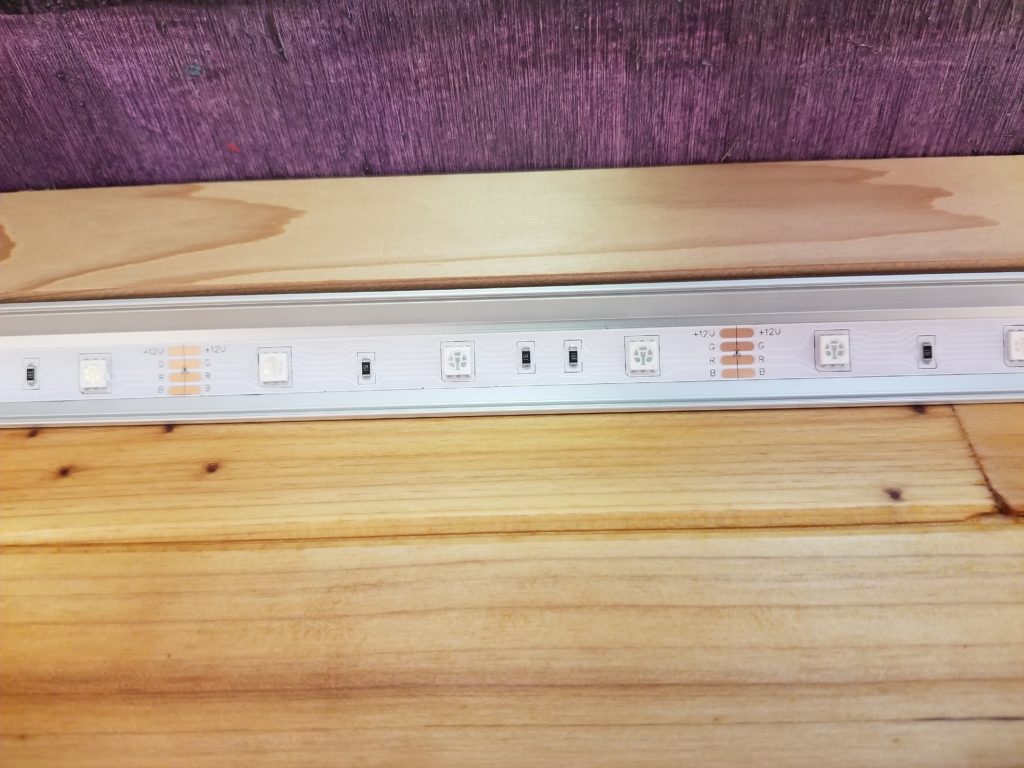
So I’m pretty close on tub preconditions. Of course, there are some things that got ADDED to the list since that chart was drawn up a year ago, too. This includes the power and lighting plan for the T.H.R.O.N.E. Room. For lighting, I decided to go with LED strips in quarter-round, corner-mounted diffuser channels. These go up against the crown molding.
This is what they look like before the round diffuser cover is installed. For scale, that’s 10cm between sections. Each of those copper “staples” is an increment of size — the strips may be cut there, and only there. So if your application isn’t an even 10cm, you just have to live with a slightly shorter strip.
I did notice something nice on the reel the LED strips arrived in..
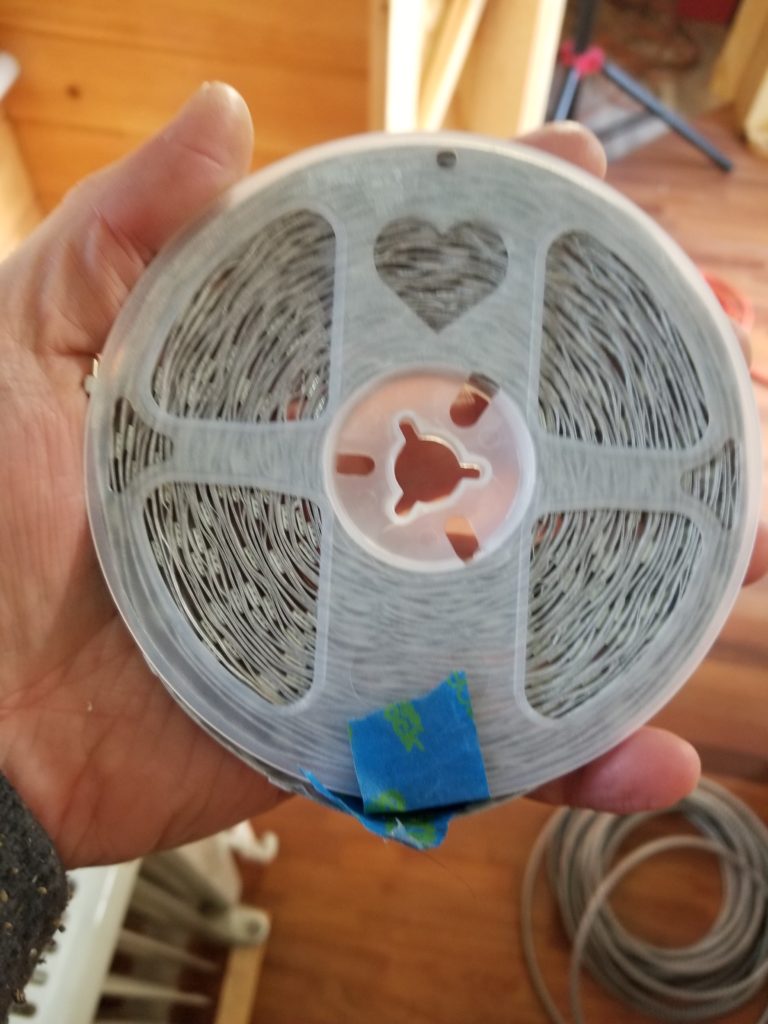
Evidently, I’m not the only one who puts a little bit of love into his work.
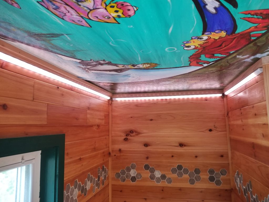
Here it is, all lit up! If you look on the right edge, at the end of the channel, you can see a dark section. I opted to have the channel fill the space rather than shorten it to match the strip increment. This way it looks right when it’s dark. Then again, it looks like there’s a single element out when it’s lit, so I don’t know that this was my best choice. Too late now.
Of course, before this could be done (well, you know). Since there’s corner molding in all my corners and this whole building has some wacky angles anyway, I couldn’t use corner pieces to join the channels. Instead, I just ran straight lengths and wired them one to the next. This meant breaking out some old soldering gear…
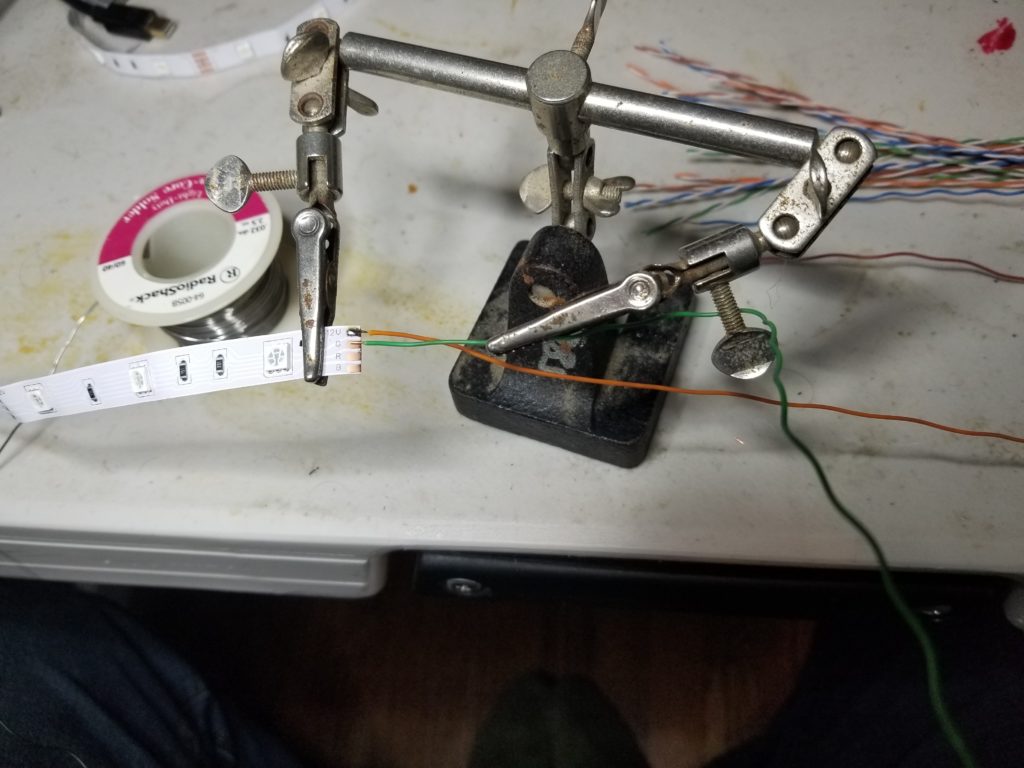
By “old” I mean I’ve had that “helping hands” clamp for at least 30 years, probably more like 35. The solder is from a store that no longer exists – remember Radio Shack? It’s their more modern graphics, but it’s still old enough to have lead in it! The wires I harvested from some old CAT-5 ethernet cable I had laying about that I wasn’t using (originally purchased to run networking in a house I bought in 1996). It turns out to have red, green, blue wires already, which is perfect. Orange is for the common power supply.
But soldering on “pigtails” is just half the story. I still need to connect one run to the next, around the corner. And in some corners, that’s pretty tight…
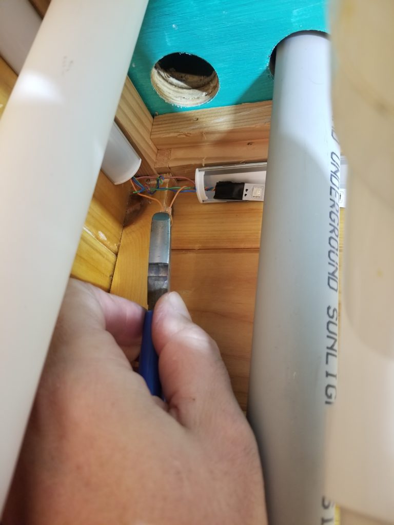
The hole in the ceiling is for the propane line. You can imagine how glad I am it’s not been run yet, as I’m squeezing my hand between the freshwater pipe and the electrical conduit to squeeze a connector on.
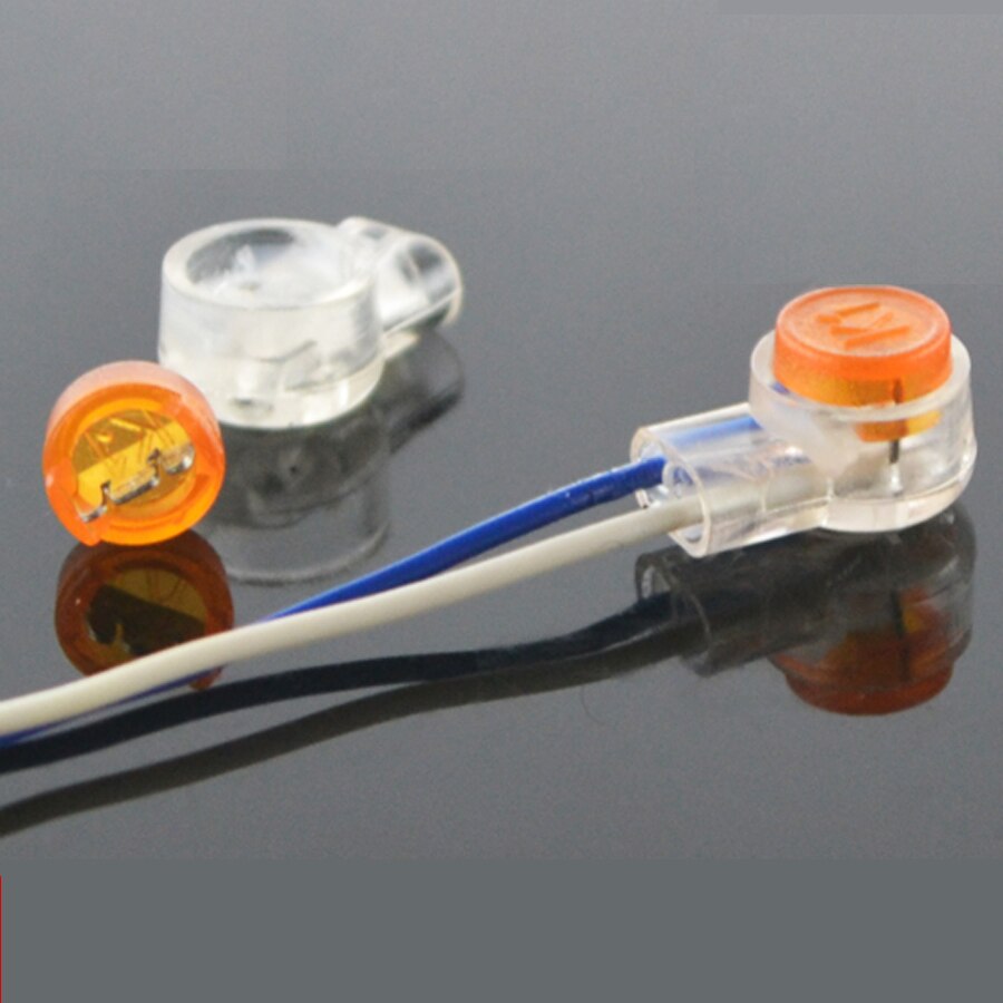
These are fun little connectors! All you have to do is slide the wires in and squeeze. You don’t even have to strip them. Little blades inside cut through the insulation for you. Perfect for this kind of thing where there’s approximately zero maneuvering room. They’re really only good for low-voltage, low-power, but that’s what I have.
All I have to do now is wire in the control panel and send a cable back to the DC Load Center to pick up the 12V supply.
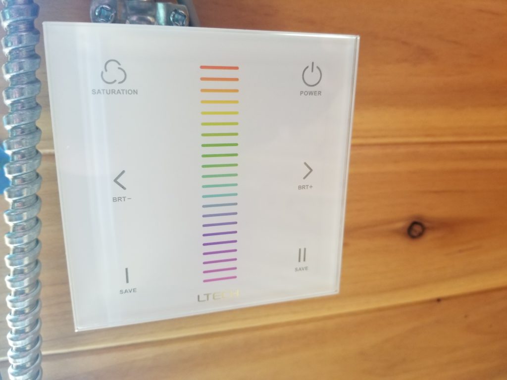
Here’s the touch panel for the lights. Hue up the middle. Brightness are the < and > keys. Saturation – touch and hold to saturate, touch and hold again to desaturate. The two buttons on the bottom are for presets.
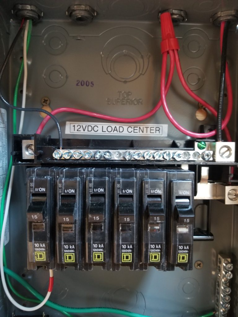
If you weren’t versed in residential wiring, this load center (“breaker box”) probably looks pretty normal to you, aside from the bold reminder this is a 12VDC system. In point of fact, most of the color coding differs from how things would go in a typical AC panel, and the way the buses are arranged is different, too. Instead of two legs of 120VAC, though, both hot bus bars are joined together to DC+. The “neutral” bus (just below the banner), has been commandeered for DC-. For safety and sanity, the DC- is bound to system ground, as well (green screw). In point of fact, the 12VDC minus is not the same as the 48VDC main battery bank minus, which floats. That’s fine – nobody references off that 48V bus except the power system, which expects this, and the 48V-to-12V power supply I added, which also expects this. All good. By the way, I did check: these breakers are in fact rated for DC use as well as AC use (it matters).
The red and black lines leaving unceremoniously through the top right are just temporary, to allow me to power the load center from a wall-wart to test things, before I have the 12V power supply wired in (and anyway, I don’t have the 48V system it runs from ready yet, either).
The T.H.R.O.N.E. Room needs its outlets before I can install the tub, though, because one of those outlets runs the graywater lift pump and its feed runs behind where the tub will go. So okay, install those next.
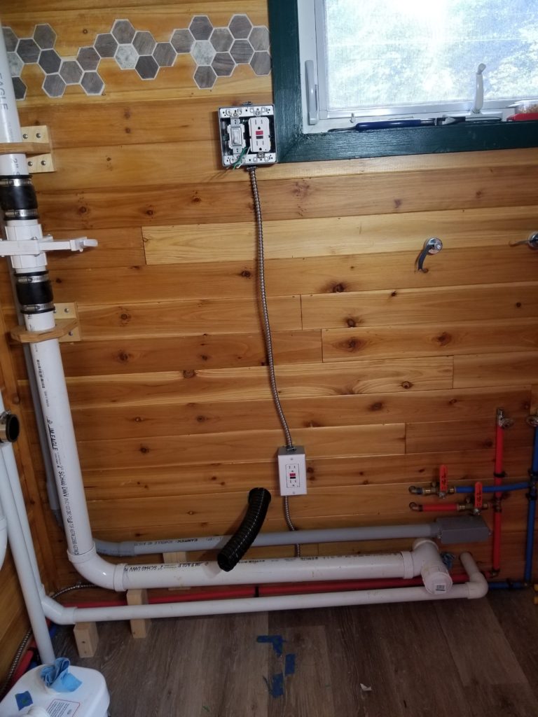
Lower: outlet for the pump. Upper: outlet for a hair dryer, charging a shaver, whatever. The switch is for vanity lights, yet to be decided and installed. I don’t need to do any of that now, just be ready for it, which is this.
For power, a line has been run from the AC load center across the ceiling in the foyer (recall this is why it had to be painted before I could finish the power before I could finish the bathroom), down the wall, around the baseboards to the graywater lift pump (a/k/a bilge), where an outlet has been installed and a line run to a person-height outlet for use by the sink. Okay. Power done.
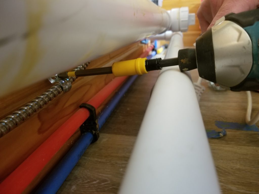
Getting it there, though, wasn’t exactly trivial… lots of under/behind/below work to do. Extenders coupled to extenders to get this screw driven, for example.
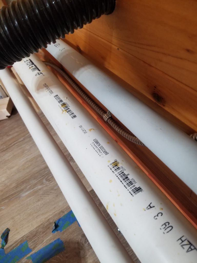
See that silver cable under there, just north of the hot water line. Yeah, that one. It would have been much easier to install it first, but I didn’t know I wanted it back then… way finding. It has its difficulties, for sure…
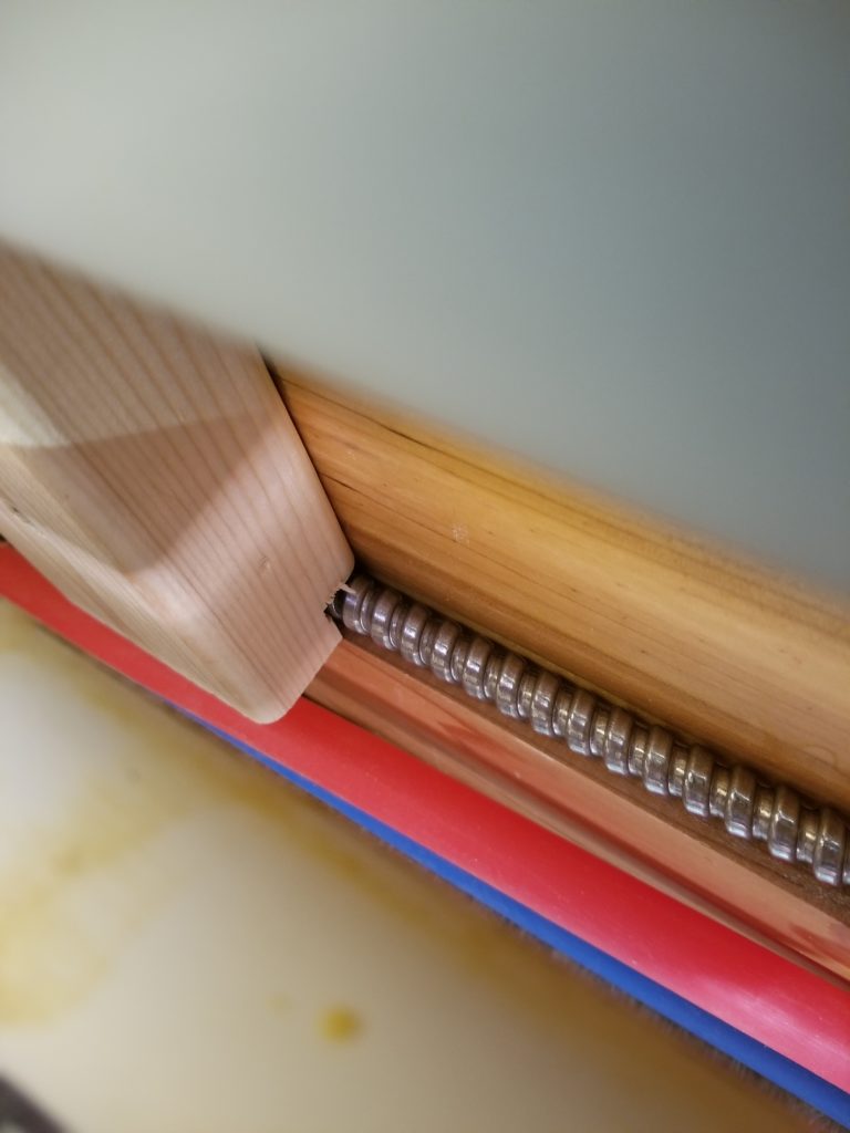
… like this one, where I had already put in some blocking to support the conduit but wanted to run the cable along the same place. Happily, this block was simply screwed in place, so I could also unscrew it, notch it, and put it back. Good thing, because the propane line is going to follow this same path and will thus motivate yet another notch!
Okay, power done!
No, wait – power’s not done! What about power for the lights? That comes a little later. It’s not a precondition for the tub.
The tub filler was actually first on this weekend’s build plan. First things first: figure out how to plumb it in (did that). Then anchor it to the floor and plumb it in. The filler came with its own anchoring kit. The instructions were in typical IKEA style (though it’s not an IKEA fixture) — namely, drawings only, no text. This international instructional style makes a lot of sense from a manufacturer’s point of view, but the lack of prose means there is often a lot of interpretation/imagination required on the part of the installer. This was no exception. There were some parts included which were not shown in the instructions and I was left to figure out how the supplied anchors worked.
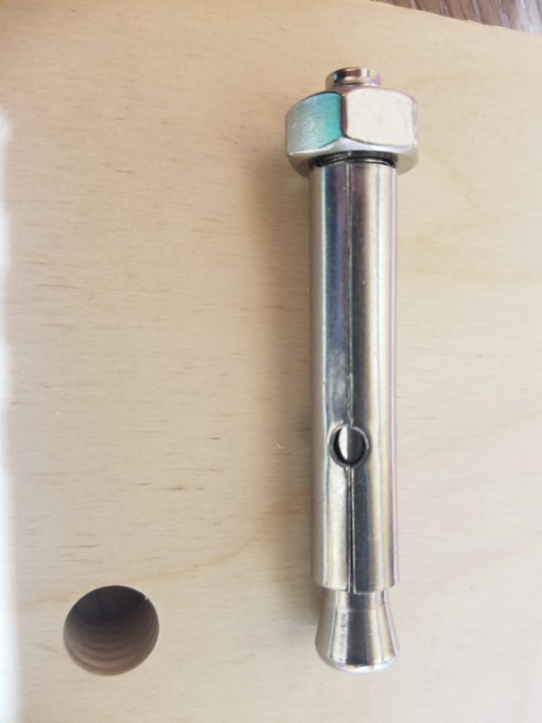
These are them. The way they work is when you tighten the nut, it draws the shaft upward into the sleeve, causing the flared end to jam into it, wedging it tightly in place. The sleeve is actually split, so it can splay as needed to accommodate the wedge and, in turn, jam in tightly to the hole in which it has been placed. Okay, got it. Time to drill.
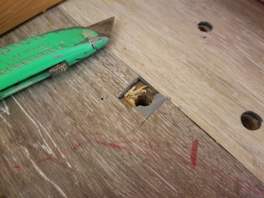
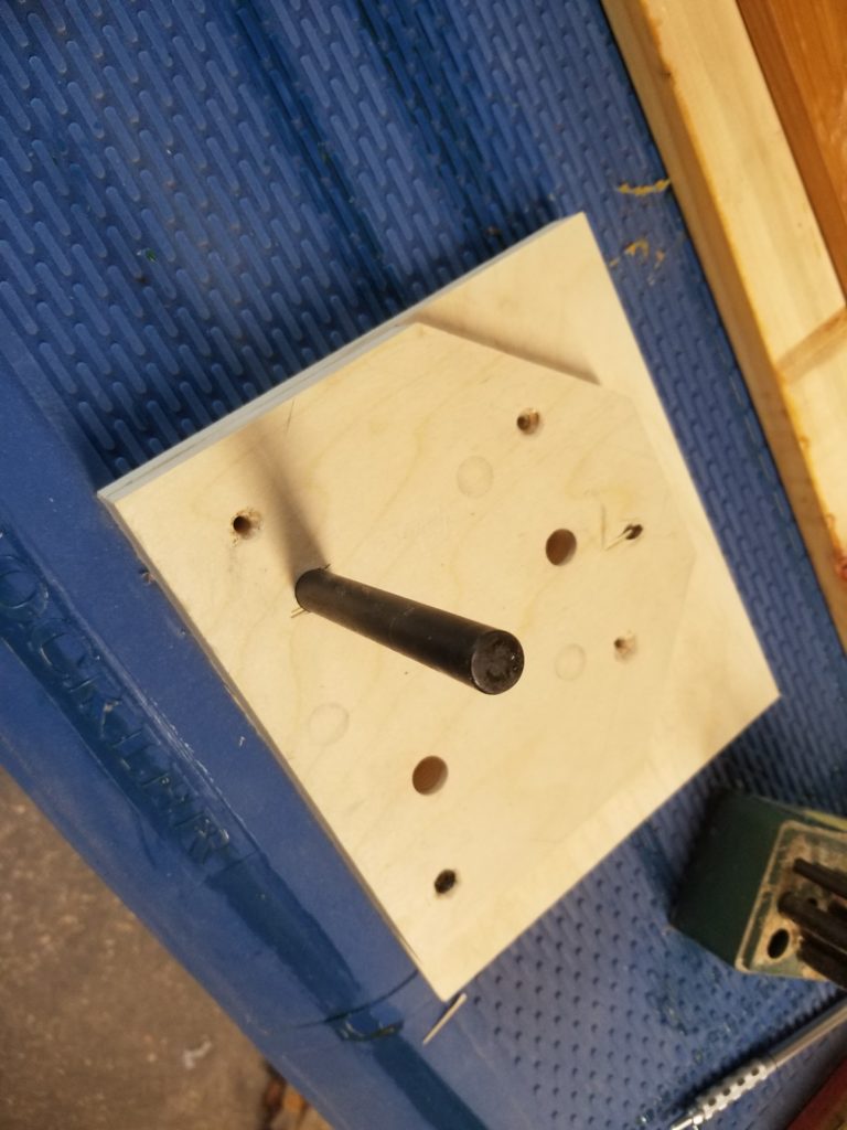
As I drill, some flakes from the subfloor get pulled up by the drill bit and , unfortunately, get lodged under the vinyl flooring, creating a bulge I cannot undo. This is not acceptable. Okay, this is going under the filler, it doesn’t have to be pretty – but it does have to be flat.
Very well, I cut out a corner of the vinyl and remove the chips. Flat now. I restore the vinyl square I cut, just for completeness, and continue the job. Then my drill bit stops before I can get to the requisite depth. What’s going on? Did I hit a screw or something? I look into the hole. It’s hard to see what’s in there. Never mind. I can shift the whole thing a little bit and drill a new set of holes, problem solved.
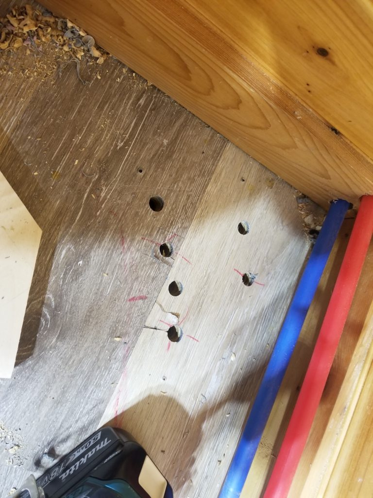
There’s not a lot of room in that corner for a new position that still satisfies the need of the tub AND doesn’t have the holes too close together such that they’d fail, but there is one such position and one should be enough. The old holes will get covered by the foot of the filer, so who cares, right? Right. Drill away.
Except not. I strike metal on this one, too. Wait, no. It can’t be that there are screws so close together in the flooring. What else is going on here? I clean out the hole and take a closer look.
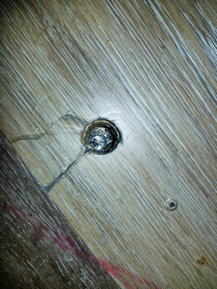
Wait a minute. That shiny metal fills the entire 1/2″ hole. None of my screws have heads that big. What is it?
Ah, yes, now I remember. It’s a cross piece on the deck of the chassis itself! This is what the floor is screwed to. Take a look in this old picture of the chassis before the floor was installed…
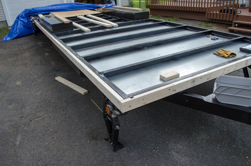
No problem. The floor is screwed down to these pretty well and drilling a 1/2″ hole through the flange is unlikely to be a problem. These cross-pieces are actually Z-shaped, so as long as I don’t compromise the vertical part, they’ll be fine. I will need some magic to get this done, though.
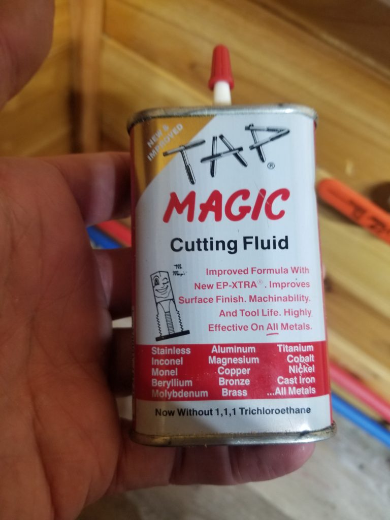
I’ve got just the thing.
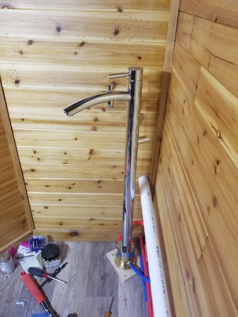
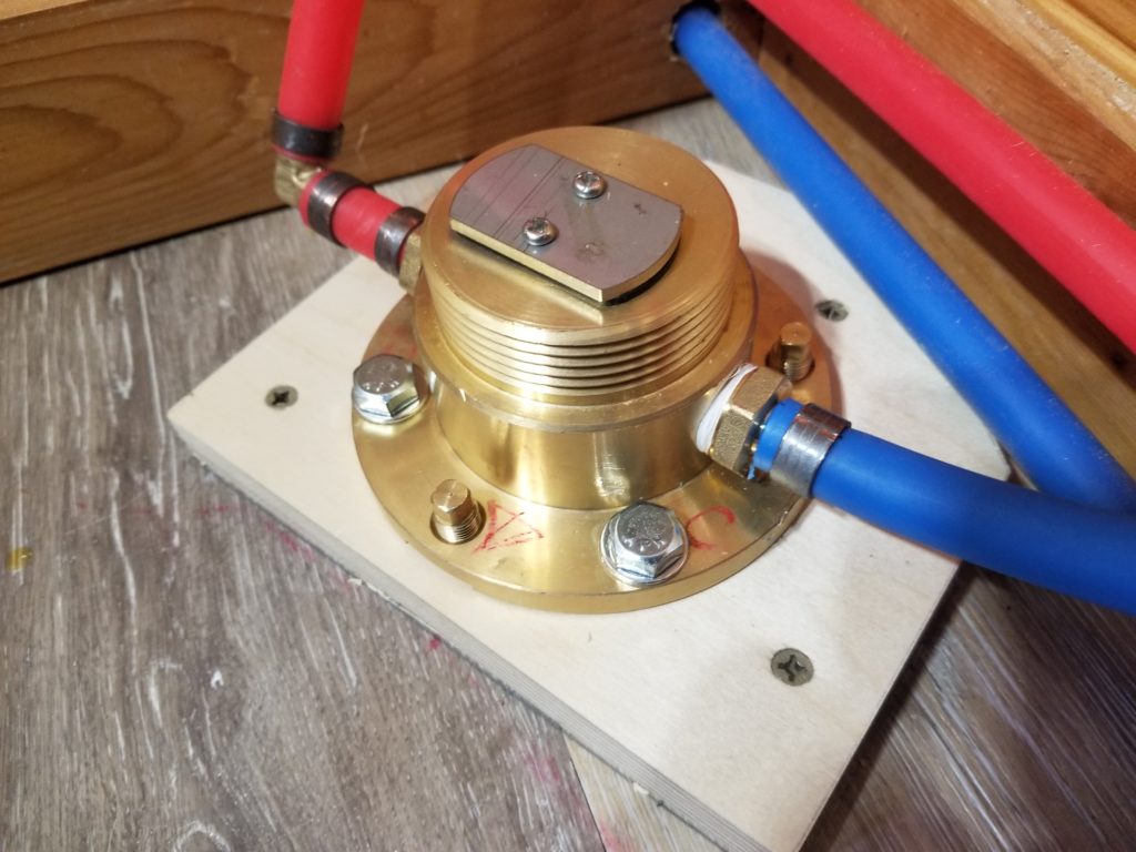
Awrighty, then. Hole drilled to depth, time to install the filler pedestal. Anchors in holes, cinched up nicely, plumbed in to the cut-off valves, which in turn are teed into the supply. Fabu – all set. PEX piping makes this look easy (and, indeed, made that part of it quick and painless).
You’ll notice a block under the filler base. That’s there to add a little extra immobility to it all, effectively stiffening the floor. The filler is 3ft tall and therefore has a lot of leverage against the anchors. I wanted to give it some insurance.
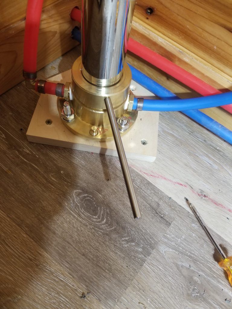
It was while tightening the collar that secures the filler pedestal to its base that I finally realized what those extra parts were for. They are chrome rods – polished and nice, so I thought they were part of the fixture proper. Nope. They fit in holes in the collar to prove some leverage for tightening it. A strap wrench would have done the trick (if I had one), but they were kind enough to include these rods as tools. If only they’d shown them in the instruction sheet, it would have saved me a bunch of wondering. Ah, well, no problem. I figured it out.
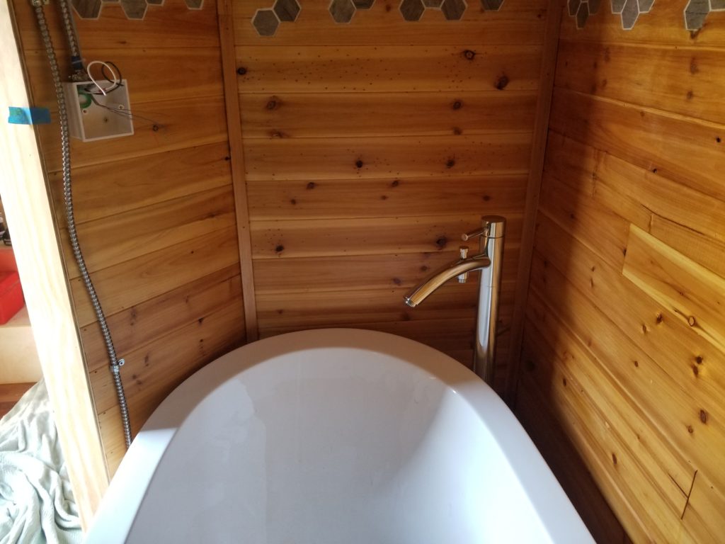
Tub filler installed!
The next question is how solid is it, really? I had my doubts about those anchors – they never really seemed to bottom out in a way that said “I’m not gonna move”. But hey, that’s what came with the thing so I used them. I gave the pedestal a couple of moderate knocks to see how solid it really was.
Not very. It came a little loose. I tightened the anchor bolts and did it again. Not satisfied. In retrospect, it’s clear these anchors are for incompressible floors like those made of concrete or mortar for tile — that makes a lot of sense for a bathroom fixture, after all. For wood, something that jams into a hole isn’t going to stay that way forever. Wood moves. This is gonna be a problem. Yeah, after all that. Shit. Okay, as we know, there are only two ways to do a thing: right and again. This is gonna be one of those “again” cases. Out it comes. I need a new plan.
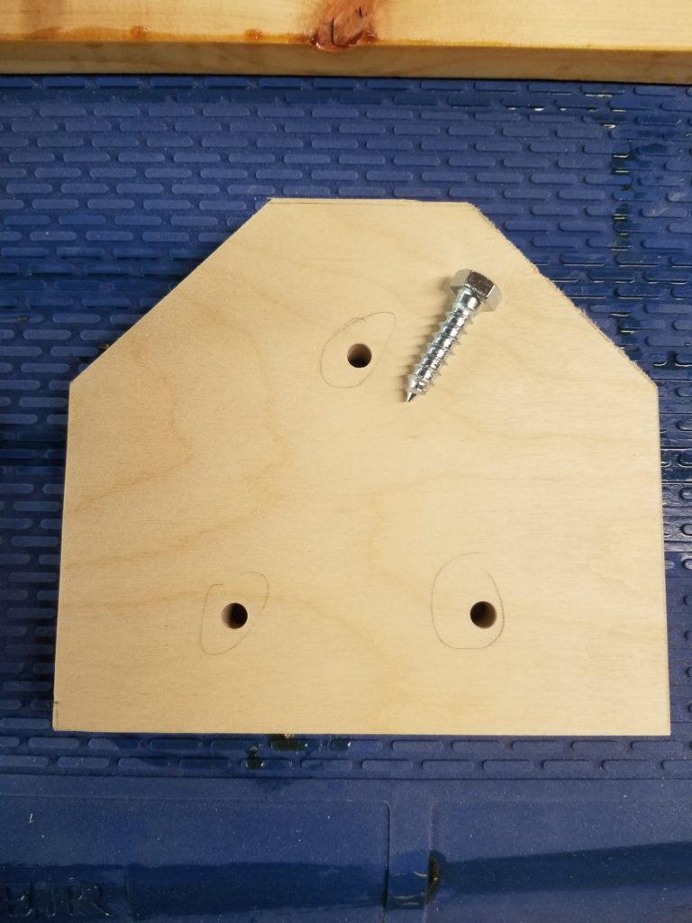
My new plan is to use some super-stiff cabinet plywood as a base (the subfloor is already too drilled out to let me attach to it directly where I need the pedestal to go), make that big enough that it can reach some fresh subfloor to be secured to, and use lag screws to hold the filler to the plywood.
I use the old foot as a template and transfer the anchor positions using a punch.
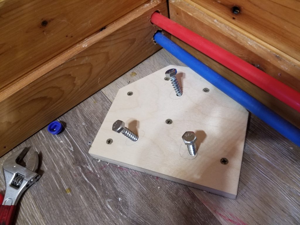
I drill new holes, carefully sized to hold the lag screws securely (after testing on a scrap to ensure perfect engagement)
The new foot is screwed to previously undisturbed subfloor in six places with heavy deck screws. The lag screws will secure to the foot which will cover, but not be affected by, those previously drilled holes in the subfloor.
Done. Again. Hopefully also “right”. I installed the pedestal and gave it a knock. Much better. It wobbles a tiny bit, but it’s stiff to the floor. The floor gives a little. The foot stayed solid to the floor and the filler base stayed solid to the foot. That’ll do. That was a lot more work than I expected it to be… but that’s how it goes. Way finding has the advantage of not requiring a complete plan at the outset, but it also means a lot more mid-course corrections are necessary.
Before pressure testing the water lines, I do also need to know the tub still fits where I’m gonna put it, after all these new bits of plumbing have been installed. I also need to know I can still maneuver it in there!
Check 1 – does the filler empty into the tub? YES. Does the tub actually clear all the pipes? Yes, if I set it off from the wall a little.
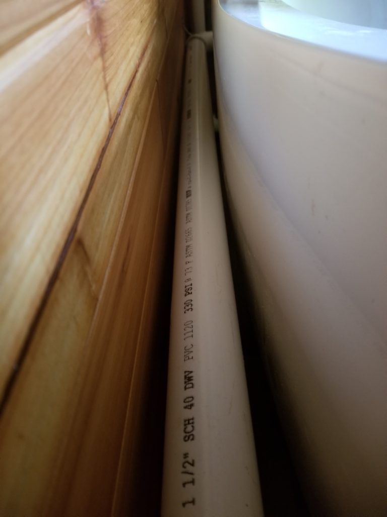
Check 2 – how tight is that drain pipe anyway? Answer: very, but it fits.
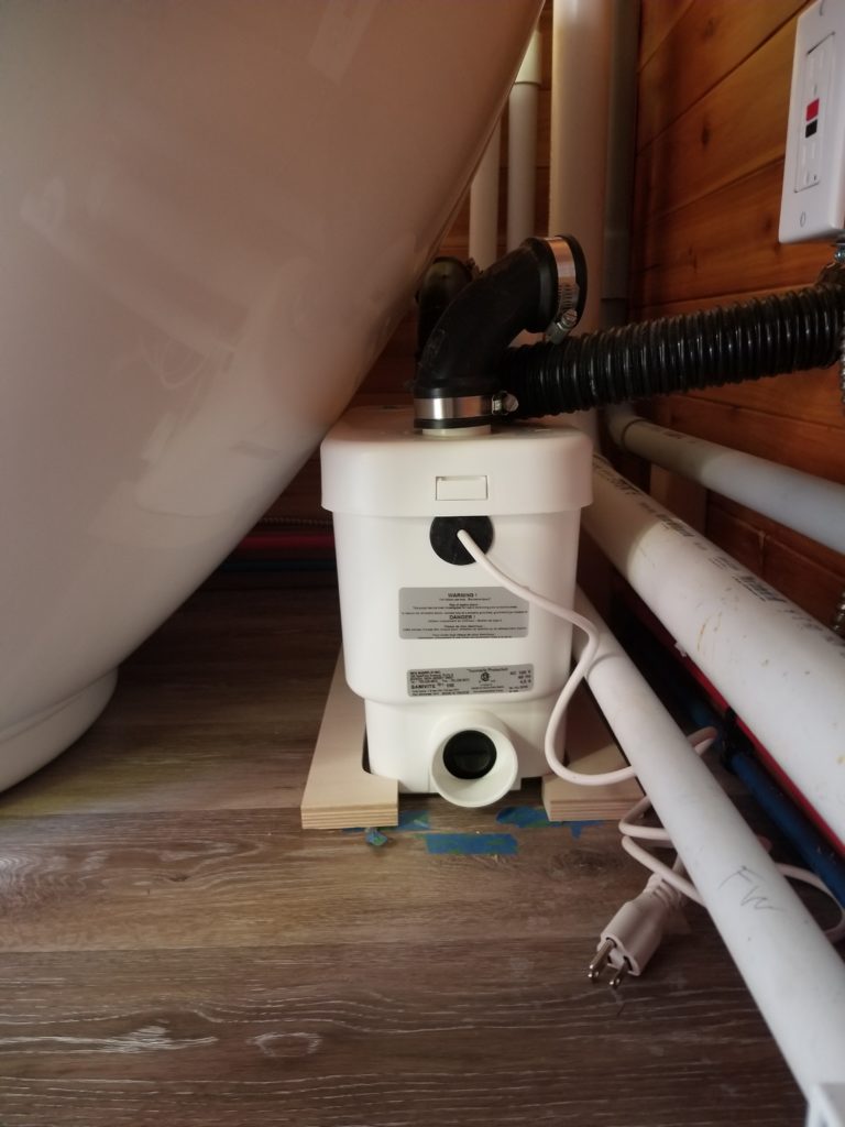
Check 3 – will the gray water lift pump still fit, too? Yes, but just barely. You can ignore the wooden blocking around its base. That’s just some layout work; the blocking for the pump isn’t done yet. I can actually move the tub a smidge from here so it’s not actually in contact with the pump housing, but yeah, it’s that close. Did I mention the house was tiny? What kind of crazy person puts an oversized tub in a tiny house? This guy 🙂
For funsies, I climbed into the tub and shot a little video from there.