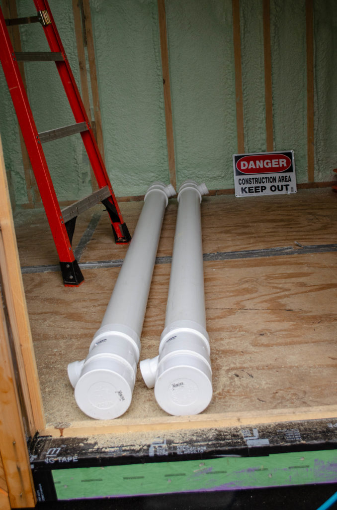
So I had this crazy idea: what if I used the empty space between the rafters over the bathroom to store my gray water, rather than taking up precious *usable* storage space with a big tank somewhere? The most rational way to use the intra-rafter space would be to run some pipes and gang them all together to become one large tank.
Okay. I start by making these 88″ long tank chambers (there will be 12, at about 4.5 gallons per each, that’s a lotta watta).
Getting the end fittings exactly 180 degrees opposing turned out to be both critical to the success of this project as well as difficult to achieve. DBS 2019-10-12.
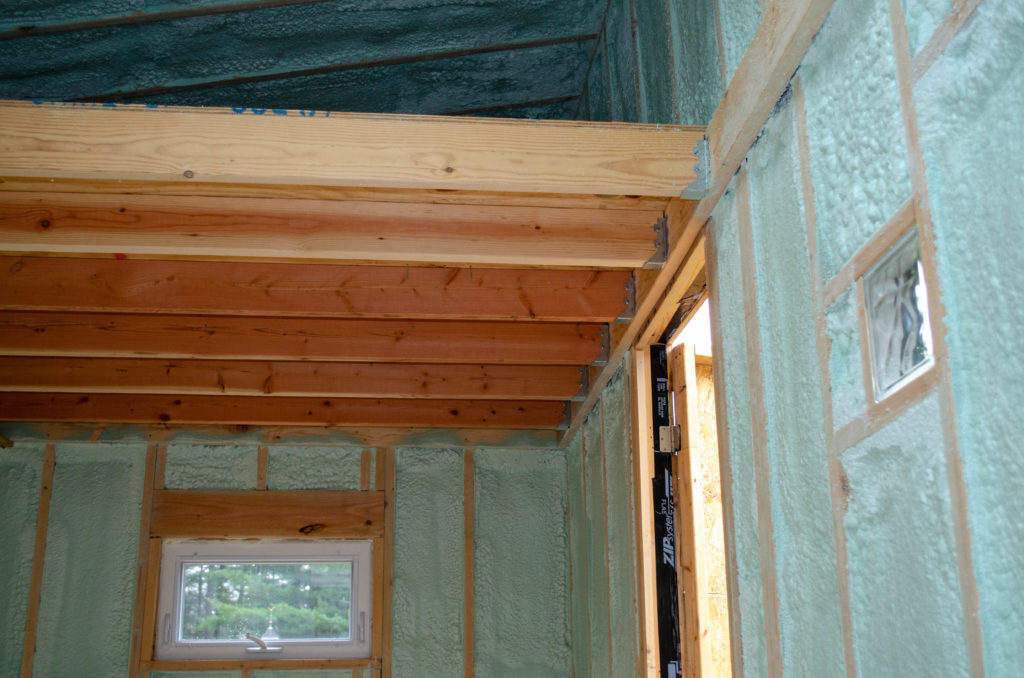
But then I have an important question. How to get those monsters into the ceiling? I mean, they’re just over 7 ft long, they have some weight to them, and the ceiling doesn’t want them yet…
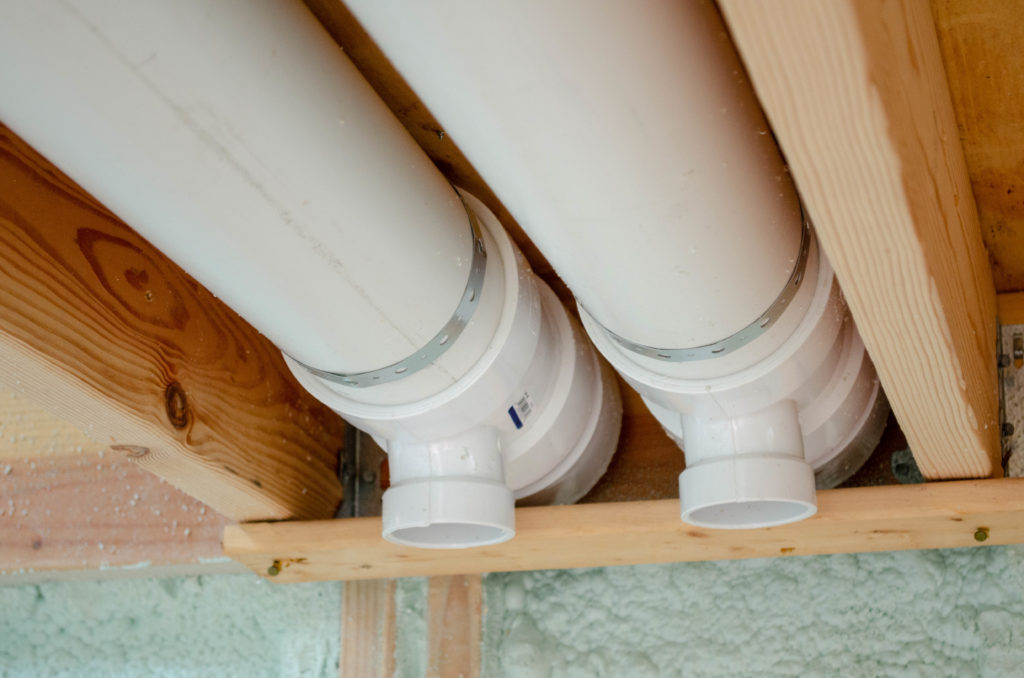
No problem! First, bang out the rusty nails from a scrap of strapping that’s been sitting under the house for a year. Next, nail it up temporarily so the heels of the tank-pipes can have somewhere to sit. Okay. That’s one end. The other side has to be supported, too, before I can strap these babies in. I can’t do like this, though, because the pipes have to clear it to get in but have to be retained once there. I can think of a couple of ways to handle this… one of which is easy.
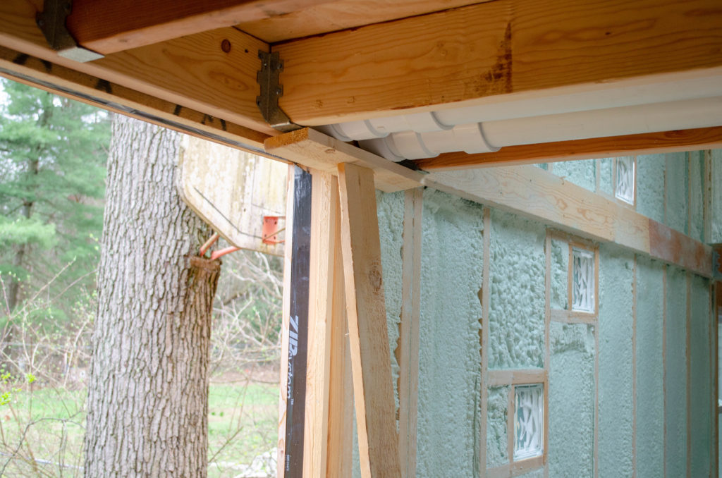
This is the easy way. A T-brace that’s just a little bit longer than the distance from floor to pipes. This way I can hold the pipes in place with my hands, then kick the foot of this brace until the whole thing was in place against the pipe heads, pressing them into the rafter bay.
In case you’re particularly astute and noticed that BOTH ends of the pipes have fittings but thie fittings on the head end (here) are not visible, I can put your mind at ease: there have been matching holes drilled in the subfloor above to accommodate the topside fittings.
Those fittings, in fact, will be how these tank chambers get filled (and vented). The fittings you can see below (previous image) are actually the drain. How they get tied together and turn this series of pipes into one big tank will be the subject of another installment.
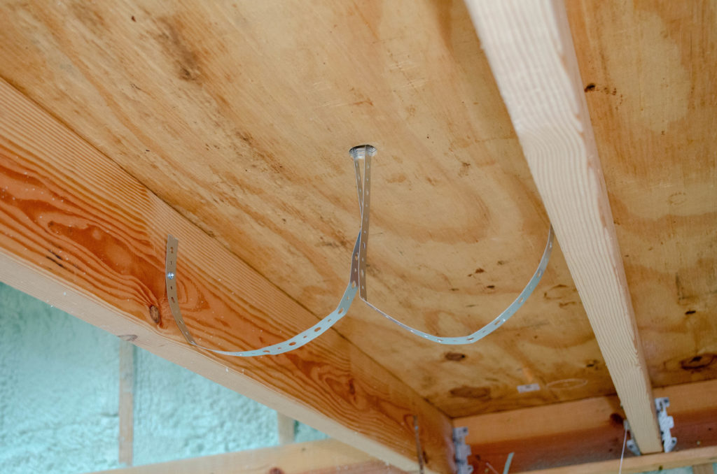
Okay, then, the pipes are in place — gotta strap them in so they’ll stay, right? Right. Some metal pipe hanger straps should do the trick nicely. It occurs to me that I really don’t want to stress the straps in a tensile (pulling-out) mode, so screwing the middle ends directly into the plywood here would probably fail. The strap would be bearing directly on the screw head and is likely to stretch/fatigue and give way. No bueno. I thought that passing the middle ends up through a hole (shown) and folding them over topside before fastening would do the trick. Indeed it did.
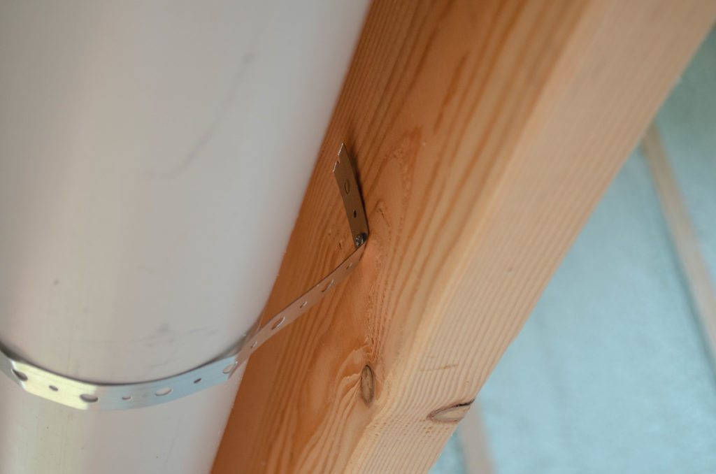
However, I didn’t realize there would be quite so much angle from the rafters to the pipes on the sides. You can see the sharp bend right there at the screw. This is the same kind of stress that I wanted to avoid when I employed that through-hole solution for the other end of the strap. Hm. Okay, then, how about putting BOTH ends of the strap through a hole and hanging them that way?
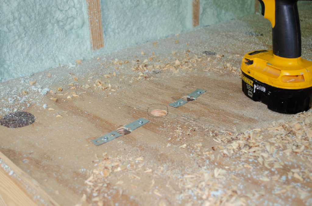
That worked. Here’s the topside view of the heel end (where the fittings point down into the room below, not up, into this space). The hanger straps happily flow into the hole, allowing the screw/strap interface to bear in a shear mode (pull across) rather than a tensile (pull out) mode. Bueno.
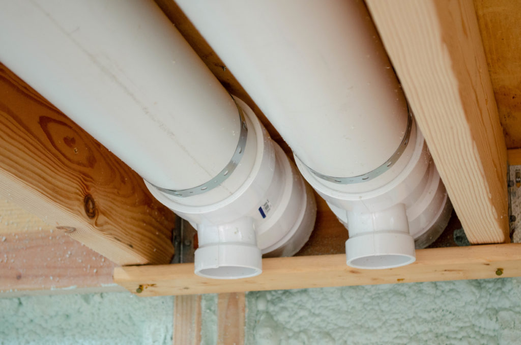
And it looks nice and tidy from below, as well, not that anyone will ever see this once the ceiling is in place.
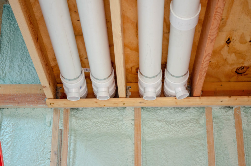
I had enough parts on hand to make the first four (of 12) tank chambers. The fill ends are not visible, behind the point of view of the photographer here. The important thing to know about that end is that there are holes drilled in the sub floor to allow the fill pipes to meet the fittings. The fittings, in fact, actually pass through those holes. That’s important context here because it means the pipes cannot roll.
Being unable to roll, it means the orientation of the pipes is fixed. It means also that three of these pipes have perfectly placed drain fittings and one of them seems to be off at a surprising angle! How could this be?
It’s tricky to line stuff up along an 88″ long length of pipe but fortunately, the pipe has some printing on it that has a pronounced baseline. I used that printing to align the fittings so the up-pointing ones would be exactly opposite the down-pointing ones (these). Perfection x3. What happened in case #4? I was just as careful to align the fittings to the text baseline.
I’ll give you a hint: the first three chambers were made from single continuous lengths of pipe. The #4 chamber is built by splicing two off-cuts together.
Since there was no critical alignment concern when joining the two sections of pipe, I didn’t give it any thought at all. Just join them.
Except when one does that, the chances that the text on pipe A is going to align perfectly with the text on pipe B is really quite small. This, of course, is a total non-issue unless one is using the text as a full-length reference line.
Which I was.
Oops.
I will need to take down chamber #4, cut it and splice it back together, this time taking a straight edge along the printing for each and extending the baseline to the edge where they meet such that I can then align them correctly this time!
I have already written the word “ALIGN!” on my other coupler, so when it comes time to join another two off-cuts, I might possibly remember this matters 🙃