Today’s update is all about the gas. We start with the furnace. After several days, I got only crickets from the manufacturer about that 6″ long 7-3/4″ inch exhaust tube, so I decided that, given the other two units inspected by my vendor also had the same 6″ long tube, that the manufacturer had changed the product without changing the document (or the document has just been wrong a long time) and what I therefore need to do is execute Plan B – letting the furnace body into the wall a bit to make up for the shortness of the exhaust tube. The furnace manual speaks of this and says up to 2″ of inset are safe to do. Examining the furnace body, I agree – the back couple of inches are not hot. Okay, then, time to make a medium hole much bigger.
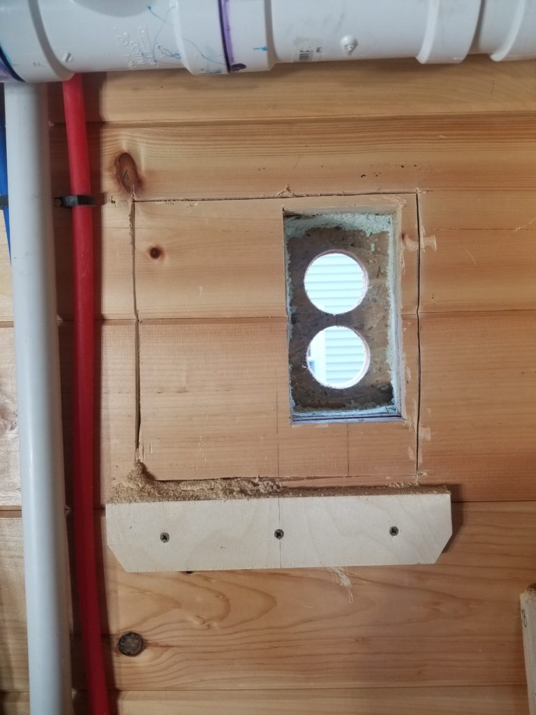
You guessed it, MultiMax is back at it. As I’m cutting, there is an area to the left that doesn’t feel the same as the area on the right. After I take the dress boards off, the reason why becomes obvious:
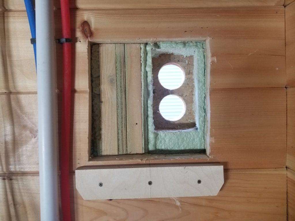
The area on the left is not just spray foam (green), it’s a double stud. I recognize it. This is one of the eight double studs that comprise the primary system by which the house is attached to the trailer! While there is now rather a lot of sheathing board also screwed into the footer which itself is bolted to the trailer, I really don’t want to cut this.
Okay, then, the question is how deep did I get by going this deep, and is that deep enough?
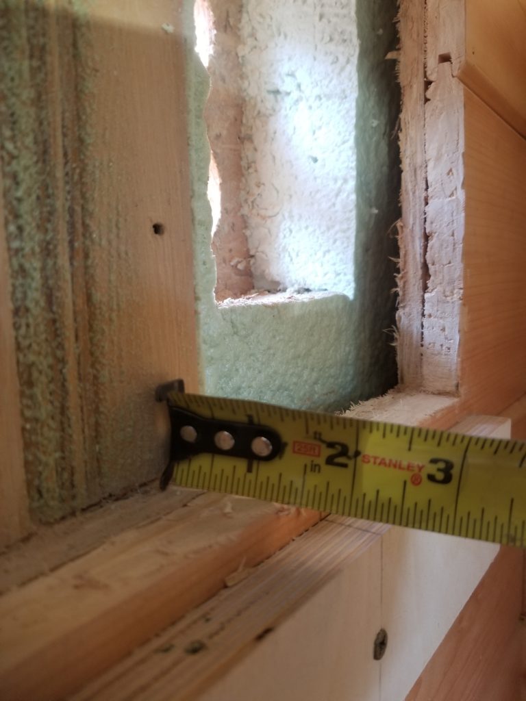
Says here I got just under an inch and a half of new depth. Well, the but of the furnace is where the exhaust tube needs to connect, the exhaust pipe I have is 6″ long (nearly), the thickness of my wall system is 6″ (which is why the 7-3/4″ tube I was promised would be perfect), subtracting 1-3/8″ for this let-in, I get… 1-3/8″ engagement of the exhaust tube with the port on the butt of the furnace. How much does it need? The book says 1-1/4″ minimum. Ha! I’ve got it beat by an eigth! Cool. It’ll work. It’s very close, but close is fine. It’ll work, and working is what matters.
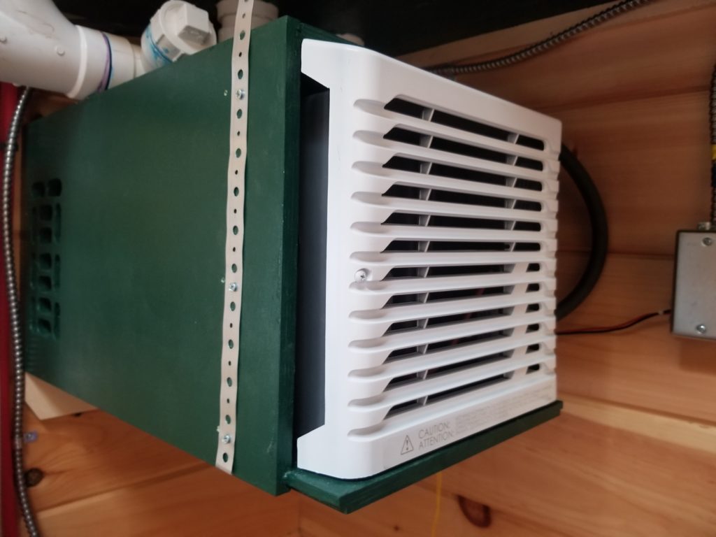
First, though, I need to adjust my furnace sleeve by the let-in depth so the holes I so carefully (and not-so-carefully) drilled in the sides will align with what they’re meant to align with, now that the furnace is going to be deeper into the wall by 1-3/8. A visit to the table saw takes care of it.
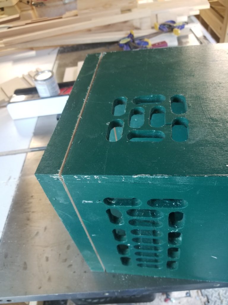
The sleeve is a little sticky because of the fresh pant, so little bits of dust stick to it readily. I tidy it up before installation, but really, I don’t care a great deal… it will be largely out of sight by the time all things are done.
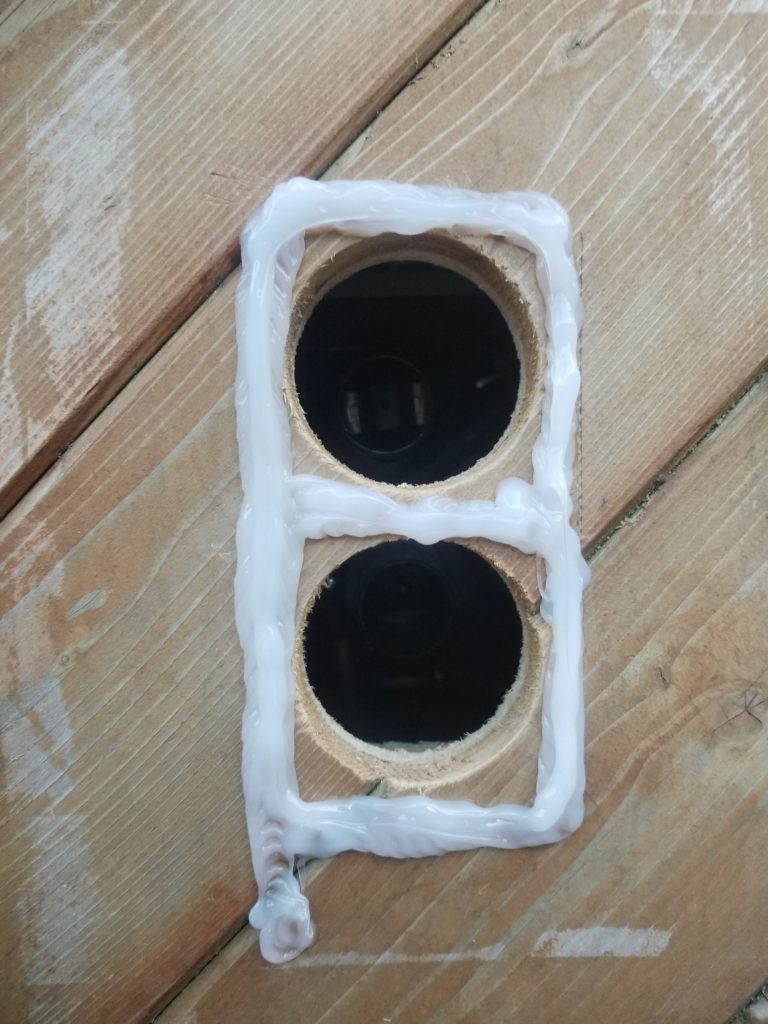
Now it’s up the ladder on the outside to goop the exhaust/intake…
And slide those vent/exhaust tubes onto their corresponding parts on the furnace (now 1-3/8″ closer than before), through the wall. Bueno. So far, so good. There’s some residue on the house from where the duct tape was holding the plastic to cover the hole while I resolved the depth issue – it’ll wear off on its own as the exterior continues to weather. No need to fuss, especially at the top of a ladder.
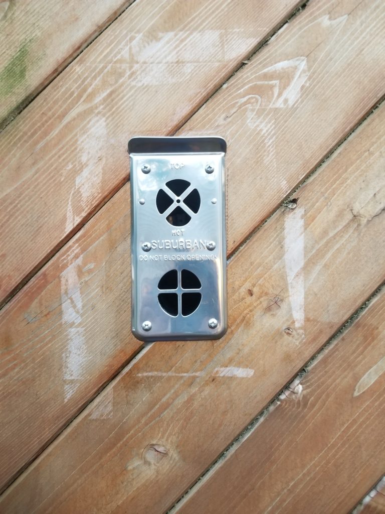
Speaking of ladder, though, there was a need for a little more ladder work! I had to cover the exhaust for the water heater (installed last year). I had noticed a water stain on the board that the heater mounts to inside. I had thought it a one-off because I saw it after a very heavy storm, but this weekend I found it wet again and decided to investigate more deeply.
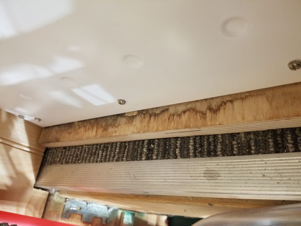
Opening the side of the water heater, I found the issue right away. Two things, really. First, a little bit of water was leaking from the exhaust port itself (see droplet where the bright tube mates with the matte tube). That wasn’t a big deal, though it did mean the exhaust was canted inward a little, rather than outward, such that any rain that made its way into the exhaust port would come into the water heater rather than draining back out. That’s obviously a problem. The bigger problem was the area around the exhaust, which is effectively the fresh air intake for combustion.
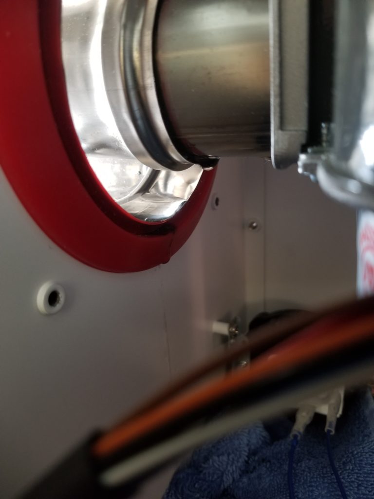
See the big red bushing? See the pool of water at the bottom of the shiny duct? Yeah, that’s a lot of water. It was raining while I was investigating this and water came in rather copiously. The whole bottom pan of the water heater was full of rain water and a little bit of dirt washed in with it. No bueno! The angle of the vent assembly was admitting water into the heater housing. When it gets really full, it leaks out the bottom and that’s what caused the water stain on the plywood mounting block. Oh dear, this is a real problem.
I checked level on the water heater and indeed, it was tipped inward a little. Worse, the vent assembly is also tipped back in such a way as to admit water. Yeah, double no bueno. I’ll need to (a) shim the water heater to be level – really, slightly better than level, with a tiny slope favoring drainage back out the fresh air intake. I will also need to simply raise the whole thing up a little so it aligns better with the hole in the side of the house where the vent/exhaust tube is mounted. That will let me make that manifold either dead level or slightly tipped up, favoring drainage back out. This won’t be particularly fun – gotta un-seal it from 10ft up in the air, go back into the house, up into the utility loft, fuss with the water heater altitude and pitch until it lines up favorably with the hole I can now see through — from the top of the ladder — up and down, up and down, up and down — until finally it’s all nicely in position, then secure the heater in place, check the angle one more time from outside, re-install the manifold, turning it a quarter turn so I can have new screw holes, and maybe after all that, it’ll be okay. It’s been raining since I discovered the problem, so I will have to wait for a dry day to go deal with this. Soon. For now, there’s a plastic poncho (plastic grocery bag duct taped) over the offending manifold to help keep the rain out and I’ll wait for the unit to fully dry out before operating it.
Meanwhile, now that the furnace is installed, I can finish the gas line work.
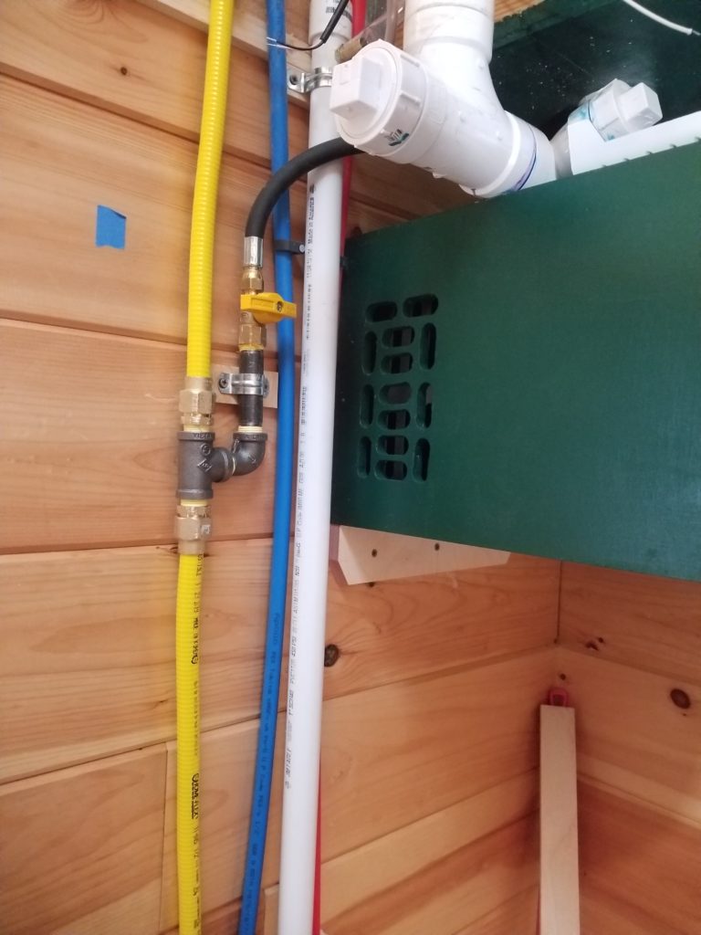
This is where the line from the stove/oven (below) meets the line from the water heater (above) and tees off to the furnace – now the system is complete, end-to-end.
I bought these rubber hookup hoses to make short work of the “last mile” between the cut-off valves and the various appliances themselves. The hoses worked great for the water heater and the furnace, but I read on the slip of paper that came with the hoses that they are only safe to about 125F. That’s fine . . . except not so much for the stove/oven hookup. I’d bet the cabinet behind the stove gets hotter than that. Not hot enough to be a Real Problem for the cabinetry, but 125F? Yeah, that seems likely. Best not use a rubber hose there. Especially if there’s a chance it will contact the back of the oven housing. Probably not super hot, but hotter than 125 is a pretty good bet. I mean, the hot water that comes out of my shower is hotter than that. Very well, old school it is: flared copper pipe. Time to buy a flare tool and learn how to use it!
For such a critical connection, it made sense to do some practice flares before committing to the supply line for the stove. Furthermore, just practicing on its end until I got it right, I might find it has become too short after cutting off my practice runs. Best to practice on stubs before going for it on the 4′ line to the stove. And so it was.
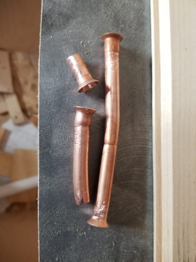
After maybe five or six tries, I got it.
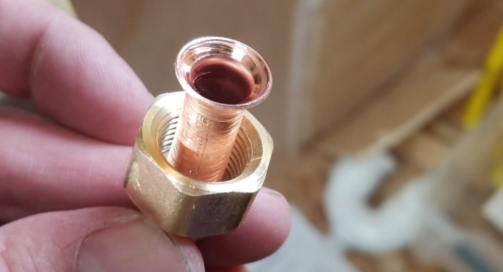
The instructions that came with the flare tool were a little bit wrong. Following them exactly got me decent flares but with some bulging below them such that the brass nut wouldn’t properly snug up against the flared end. Using my brain, some slight adjustment to the process got me this beautifully flared end without any bulges.
Time to hook up all the appliances, then, and test my gas system! This task (and actually firing them up) was on my list of Big Scary Things (a few of them have already come and gone without incident). I’ve never done gas fitting before. I understand what needs to be done and how to safely test it before use, but still… I’ll admit to being a bit nervous. First, though, time to test for leaks. I hooked up a 20# propane tank from my grill (why bother filling my 40# house tanks for the test?) to the house and went at all the connections with three leak detection tools, two of which are shown here:
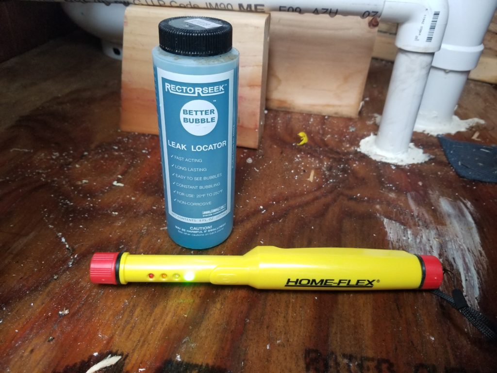
The blue bottle is glorified soapy water with a thickener. Daub it on the gas fittings and look for bubbles when the system is pressurized. The yellow wand is an electronic sensor that claims to detect propane gas. The third leak detection tool is my schnozz. Propane, like natural gas supplied to houses, has an odorant added to it to aid in leak detection. Okay, then, one by one I visit each fitting, lather it up with the blue stuff, wave the magic wand over, under, and around it, and furthermore give it a mighty sniff with my snout. Only ONE of the joints had any leak at all and it was one of the copper ones. I was especially careful not to over-tighten these, as that can do damage, so in this case I had under-estimated the torque a little bit. No problem, turn off the gas, tighten it a quarter turn with a wrench, and test again. Now it’s perfect. My gas (test) passed!
And now… now it’s time to actually fire up (literally) the appliances and see that they work. The water heater has to wait due to the rainwater issue, but the furnace and stove/oven are ready to test. Well, they will be once I hook up their electric supply, which I do next (nothing interesting to show about that – same old same old – BX cable to junction boxes to appliances). One thing that is a bit frustrating, though, is a total lack of standards regarding color codes!
One appliance had a red wire for DC+ and a yellow one for DC-. Another had DC+ in black and DC- in white. That echoes the color code for residential AC work, but in DC land, black is usually – and red is usually +. Nope. Not here. Furthermore, in my DC distribution, I am using cables normally used for AC, so they have black and white wires… and I decided that black was DC- and therefore white had to be DC+. To avoid confusion, I put some red tape on every single white wire at the point of use, so there’s no question that it’s DC+. Still, there’s plenty of confusion at the appliances. I use some colored tape to indicate mating wires when the wires themselves are different colors (e.g., black tape on the yellow appliance wire that’s DC-, mated to a black wire which now is consistent with my system color scheme). There was a lot of that. I didn’t take pictures — too busy doing it and the connections are in dark spaces anyway, making them challenging to photograph.
It was all done, finally, and now the moment of truthiness! First, though, SAFETY PROTOCOLS! For this I enlist a helper whom I instruct on how to turn off the gas supply, how to use a fire extinguisher (which is standing by), and furthermore we have a pressurized and ready garden hose for emergency response, as well. For me, I have a face shield on, leather gloves, a canvas apron, and the windows open. I talk it all through as I go, so my helper knows what’s going on. “Turning on power to the stove!”. “Lights check out okay – no problems”. “Turning on gas to the stove!” “So far so good”. “Now gonna light it, stand by!”. The stove does not light.
I am not surprised – the gas line is still mostly full of air. I need to let the gas push out the air, but obviously don’t want to just leave the line open, either. It takes a few attempts at lighting the stove before one of the burners lights. Then the next. Then the next! Everything nice and orderly. No issues.
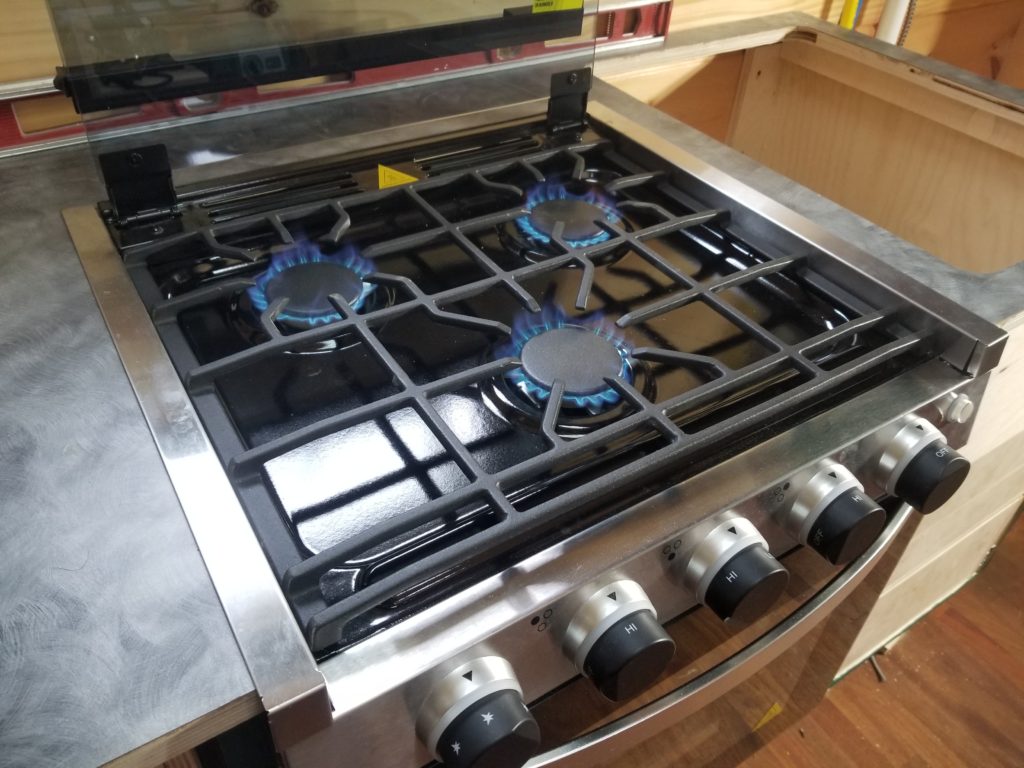
And while I was not actually cooking, NOW I’M COOKING WITH GAS! As the saying goes 🙂 The oven takes a few tries to light, as well, for the same reason (need to purge the air from its feed tube). It, too, however, lights and runs. I don’t leave it on for long – no need to waste dinosaur ghosts. I just need to know it works. It works. Totally drama-free, just how I like my gas work.
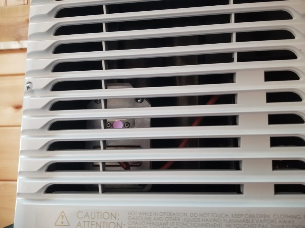
How about the furnace, so long in the doing? It fires up right away when my pretend thermostat (a pair of yellow alligator test clips) calls for heat. It takes a little while for the air coming out to get warm, but it does, and the spyglass definitely shows flame (round portal, through louvers).
The furnace makes considerably more noise than I expect, especially given it’s the “quiet” model from the manufacturer. There’s a bit of a buzzing it makes, too, that I’m not certain is okay. I’ll need to investigate that a bit. I really don’t want to un-install it, though, as that would require re-sealing it from the outside, with the possibility of stripping the screw holes (can’t rotate the ducting here, since it’s not just a circle). I know how to deal with that, but I really would rather just not have to, ya know? Maybe it’s the fan nipping at the housing? Hard to say. I think I can probably stick a dowel in from the front (grille removed) and twiddle the fan. That would tell me if I had an issue worth the trouble of dismounting it. If it spins freely, maybe it’s fine and just buzzy. There’s a particular passenger aircraft by Airbus that is just buzzy. I’m glad the furnace is mounted as far from the sleeping area as possible, though, given its noisiness.
Remember I said I was waiting on installing the sink because I needed access to the gas line? Here’s a vivid comparison of the two ways to access this area. First, with the sink absent, I can just lean in from above and do most of the necessary gas and electrical work in relative comfort.
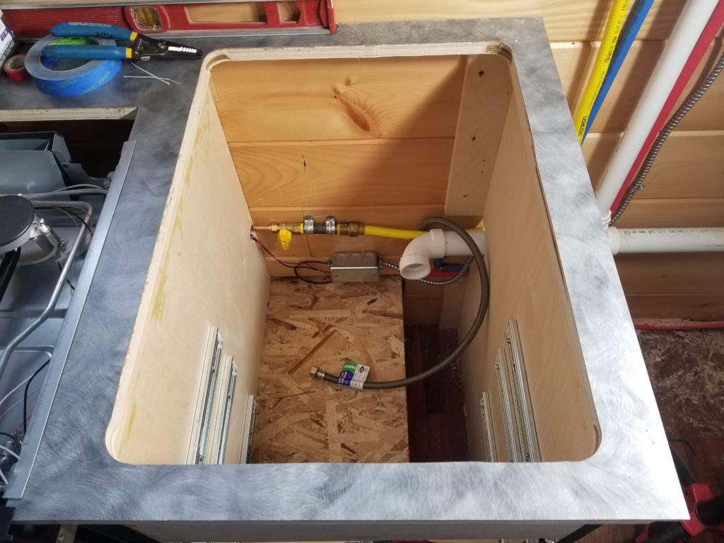
If the sink were in place, this is the only way in:
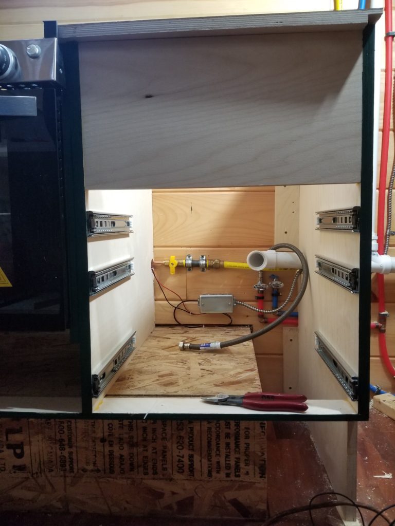
That panel across the cabinet is the same depth as the sink. The wall is 24″ from the front of this 16″ wide cabinet. The floor of the cabinet is itself 10″ from the floor of the house. I actually can get my body in there, kind-of, but who wants to work in such a cramped space, constrained on four sides? Working from above was much nicer. If I remember correctly, I could even install the electrical junction box from above, even given its position so low on the wall.
But now that the stove/oven is happy and all the rest of the things that happen here (except for the under-mount slides for the skinny slide-out I am going to put in that odd-shaped bay to the right, below the main deck of the cabinet), it’s time to actually install that sink! By the time I get this far, I’m pretty much done for the weekend.
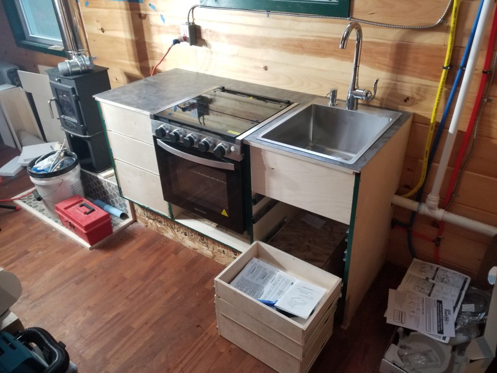
It is, however, eminently satisfying to have it in place. I will finish assembling the faucet (needs the extension head installed and the supply lines connected) and plumb in the drain another day. One cool thing about the soap pump… instead of an integrated bottle, it actually has a long hose that can be dropped right into a big bottle stored under the sink. Perfect! Far fewer refills, never over-filled. I like it! Now if only the topside parts were made out of metal instead of thin plastic that has been made to look like metal… I worry that it won’t last long. However, it’s too late now! Swapping it out would be a huge bother given the body of the sink being such an obstruction and the narrowness of the cabinet. It could be done with patience, a basin wrench, and a mirror… but I think I’ll wait on that until if/when it fails. For now, I’ll just be gentle 🙂 Or maybe now that I see how this pump works with its feed tube and check valve, I’ll scrap it, in favor of an all-metal one, even with the bother of swapping it out at this point (the sink ain’t going anywhere – it’s sealed in), and just find a way to use the feed tube with the all metal one. Hm. I kinda wish I’d thought of that two hours ago (before the sink was committed with adhesive sealant to the countertop). I’ll think about it.
By the way, that’s not the final appearance of the drawers, either. They’ll get dress fronts that cover the gaps made by the slides. But not today.