When we last left our intrepid electrician, he had just received a new 6kW inverter and was contemplating wire upgrades for the breaker box (“load center”) to handle the 100 amps the dual inverter system could supply. If you’re doing nerdful math in your head, you may conclude that 2x 6kW inverters at 240V does not imply 100 amps and you’d be correct. The sustained power rating is 6kW each but they can peak out at 12kW for a while. 2x 12kW @ 240V -> 100 Amps.
At the load center side of things, I’m going to need to swap out my 60-amp panel for a 100+ panel, as well as upgrade the wiring that goes to it. Let’s start there. This is the old panel, on the left.
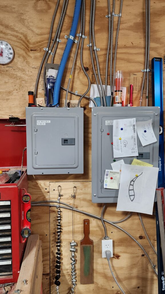
Take it out, label all the circuits, hoping there’s enough wire to reach the breakers in the new box.
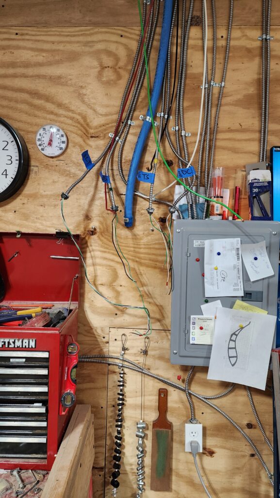
The blue conduit used to have #6 wire in it, which was totally appropriate for the 50A service. But now I need 100A wire. That would be #2, which doesn’t look that much bigger, but it is super stiff and thus impressively difficult to run through the conduit, which is big enough technically but tight enough that if the wires should cross enroute, they jam, making it exceptionally difficult to thread them through.
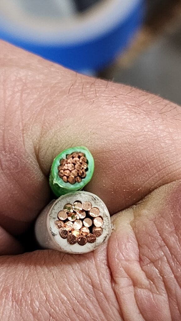
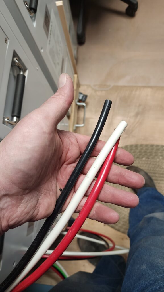
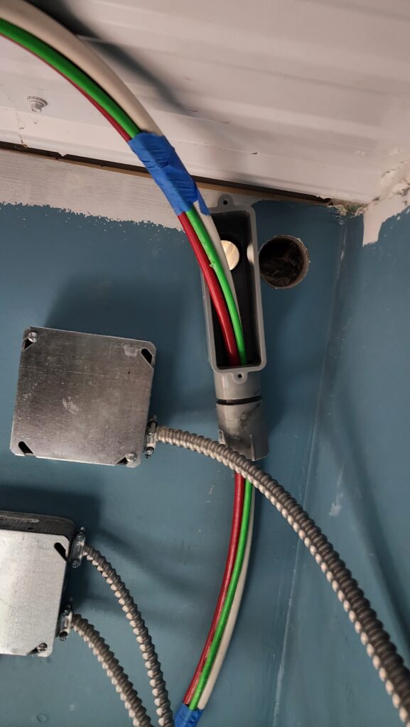
What was hardest was getting them to change directions, like where the conduit passes through the wall from the shop to the office, where the inverters are (rightmost image). You can see the daylight in the background, behind what is actually four wires. They did not at all want to bend in such tight quarters. This is the office side, in the ceiling. The workshop side was just as difficult to get them to bend downward and into the conduit.
Indeed, I wound up doing this backwards. I dismounted the conduit, laid it flat and straight, then pulled the wires through that way, because they would NOT be pulled around curves given how close the fit and the stiffness of the wires.
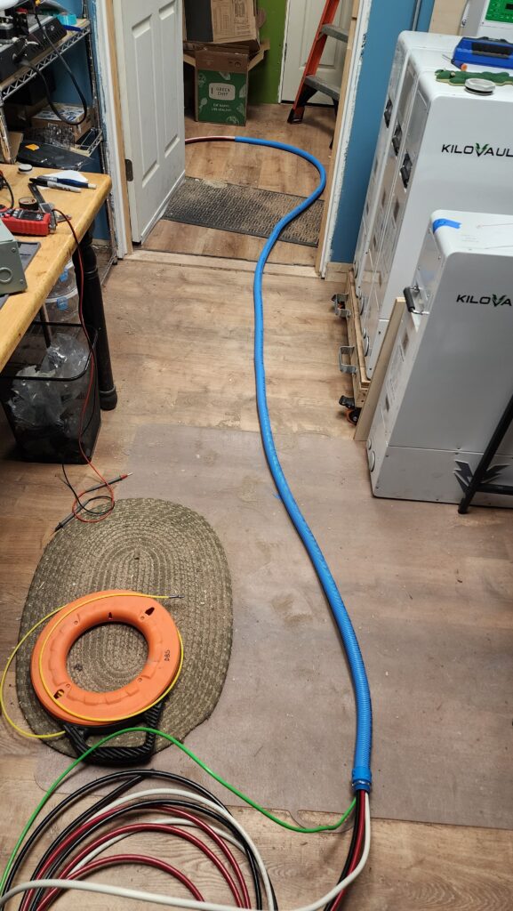
You can see how full that conduit is! Not much room in there at all. Then I took the wire-filled conduit and attempted to install it in place. With 30 pounds of wire already in it. At the top of a ladder. This was not a good time. This is a view from below showing the same corner of the ceiling as that right-most photo in the series of three, above.
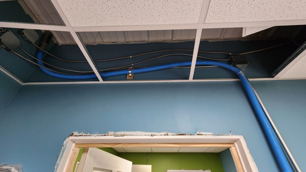
As an aside, you might be wondering why in the nearly 3 years I’ve been here, have I not put trim around the door. The answer is I don’t like the door and plan to replace it, then add trim. But other things have had priority, so it’s still the old door and it’s still not trimmed. All in due time.
The heavy blue snake was a real beast to install without damaging the suspended ceiling and without its considerable weight simply pulling the whole thing down to the floor.
I got it done, but did not have a good time doing it.
The good news is that on the workshop side of this, the new 120-amp load center went in easily and I’m pleased to report that the wire ends were all long enough to find their way to the new breakers, even though the panel was a bit larger and required a longer reach than the previous one. I happened to have left enough play in the wires that it all worked out. Every now and then you get lucky.
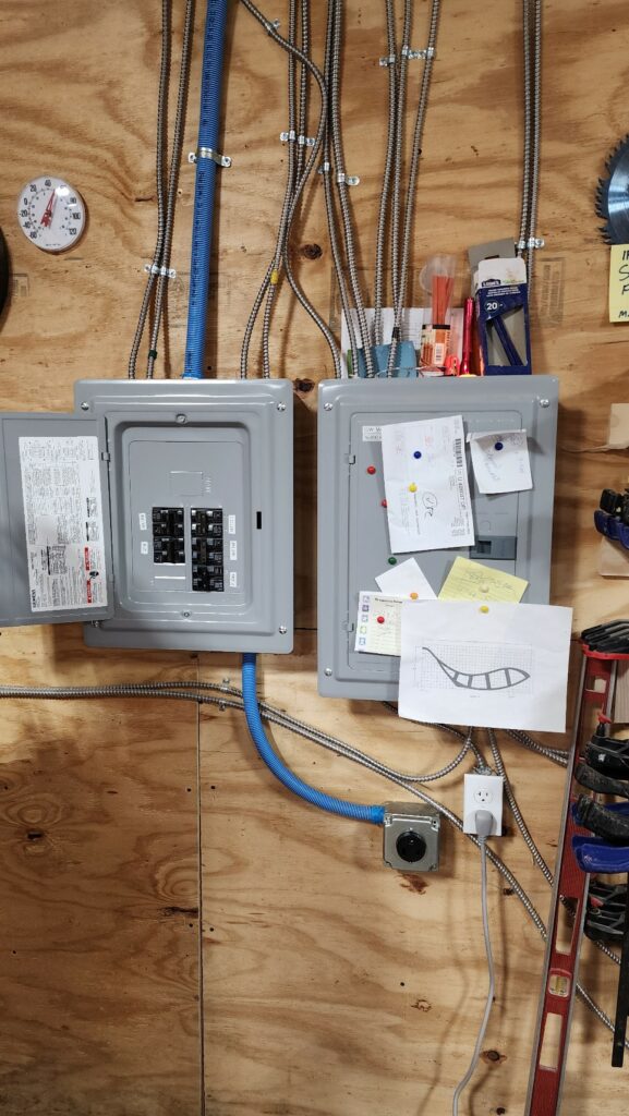
You might be asking why I didn’t just get another large panel like the other one, so the two would be the same. This is an excellent question and I do not have an excellent answer for you. I chose this panel because it had the power and circuit capacity I needed and didn’t really think about how the two would look side by side. If I had, I would probably have gone for the taller panel just so they’d look like more like a matched set, even if they are usually obscured by my tool chest.
The astute observer will note the NEMA 6-50 outlet added to the system at the end of the curved piece of blue conduit. What’s that for? That’s a massive outlet and I haven’t told you about any new major machinery. You’ll see what that’s about in a bit.
But first, a nice little detail. See that red thing?
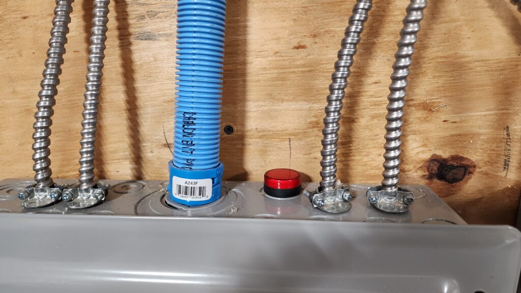
That’s a light which is wired directly to the 240V feed. When the panel is energized, the light is illuminated. I normally leave this system off so the heavy machinery power supply doesn’t consume battery power keeping its circuits ready when I’m not working in the shop. The light reminds me to shut that system down when I’m leaving the shop. It also tells me the panel is energized — or isn’t — so if a machine isn’t running, I’ll know whether the system is down or it’s just one circuit that’s tripped.
Okay, new 120A load center is in and re-connected to all the circuits (and the new mystery outlet). The 100A wire has been run back to the office at great effort. But what still needs done is stacking the two inverters together so they share the load and can even supply that 100 amps when called for.
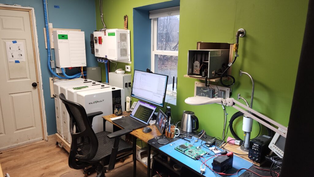
Let’s begin at the begining. The batteries. Recall I now have four of these, but my battery dolly only has room for three. For that matter, there isn’t room in the room for three, either. Here’s a refresher: one battery is on the floor, not on the dolly, and they’re pulled out from the corner because all four can’t fit next to my desk. This has the batteries a bit in the way of the door, as you can see, aside from not being able to move them in and out together on the dolly, which is necessary for occasional service.
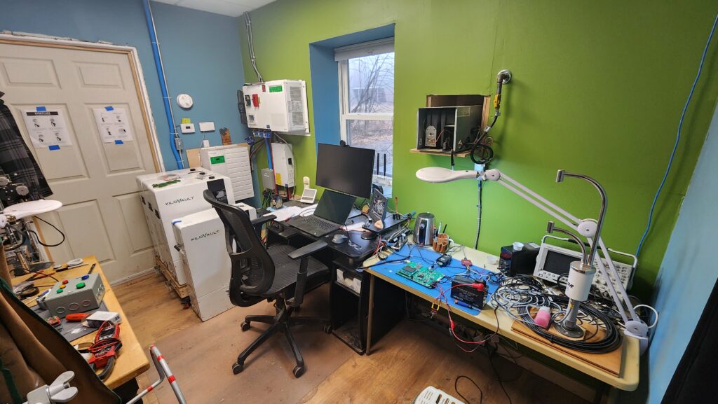
So before anything may be done, something else must first be done. In this case, that means making my desk & work table more narrow. It’s a plastic table, so there’s no changing its length. The desk is kind of complicated. I thought about trying to rework it to be a foot narrower, but that was going to be a fair bit of work and might not have succeeded, given how the desk is built. Hm.
The answer was to not modify the desk at all, but to remove the plastic table, convert the desk into the work surface, and get a new, narrow desk that fits the space.

That at least made it possible to fit the batteries neatly where they go, but I still need to make a new dolly that can handle their collective 920#.
So I did. 3/4″ plywood, 2×4 studs. 1000#-rated casters (not shown), reclaimed from the prior dolly.
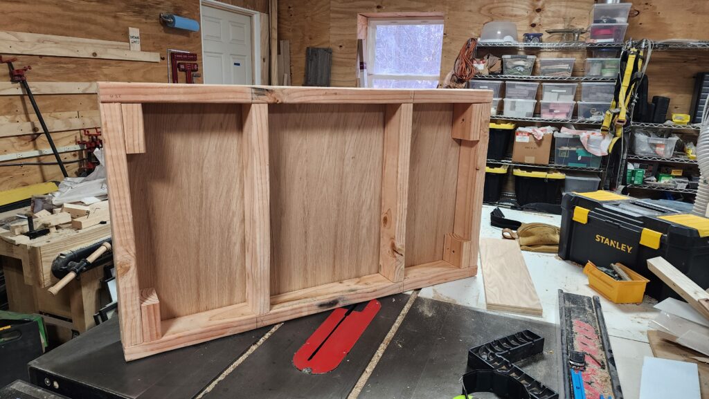
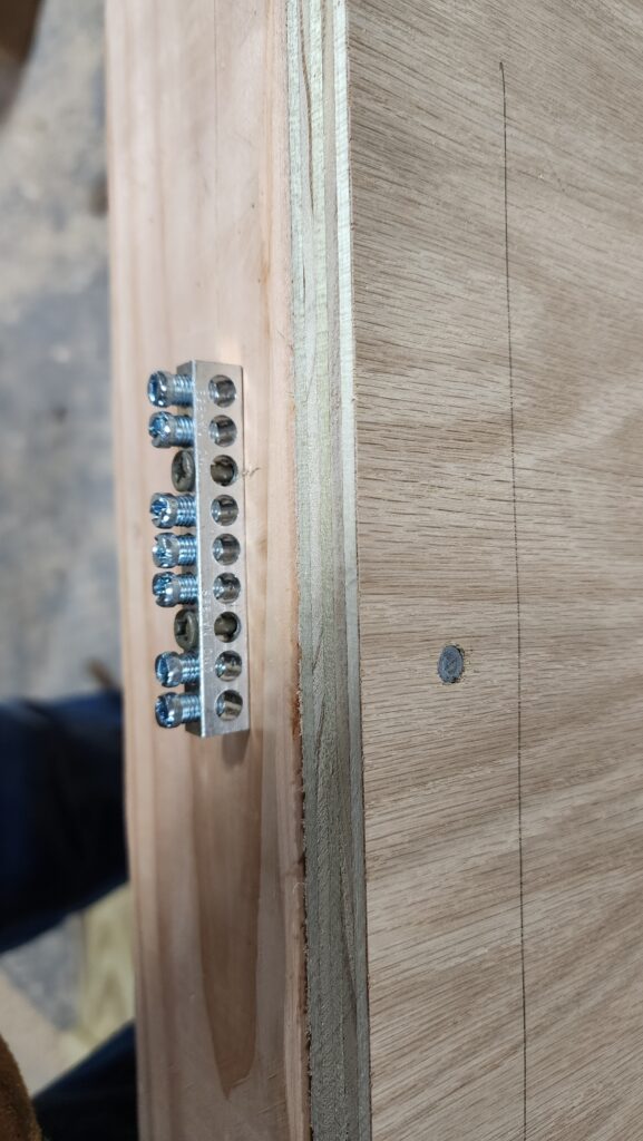
Nothing fancy, but it gets the job done. I installed a screw-type bus bar at the end so I could connect their ground wires all together and just run one back to the system ground, rather than having to fuss with four wires. The pic on the right shows the batteries on the new dolly. The gray wire is the data connection where the leader and the followers talk about important system management things.
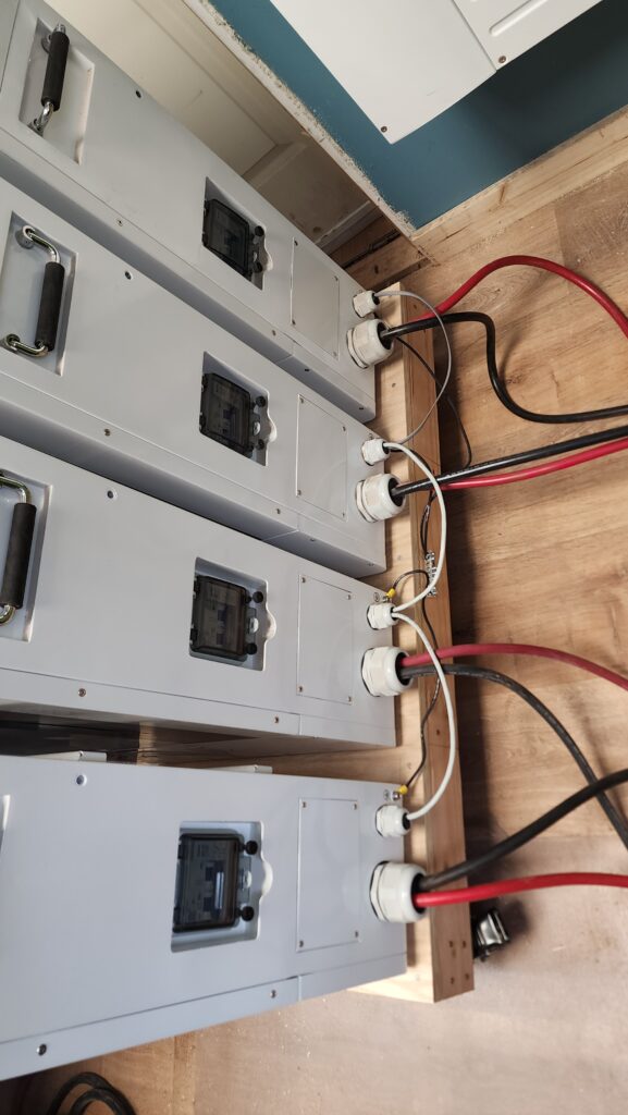
With 920# of batteries plus the considerable weight of the dolly itself, I’d guess this thing is getting pretty close to that half ton rating on the casters. These casters are my favorite ones and are industrial grade. They took this load like the champions they are. No problem rolling this half-ton rig around.
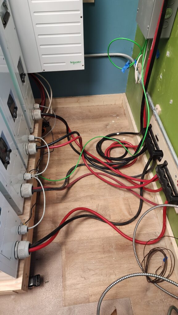
One of the problems with having started with 2 batteries and then 3 and now 4 is that the battery hookup bus bars were positioned to be centered on two, not on four, and being off-center means I can’t pull out the battery set as much as I’d like because some of the wires limit the travel due to their length. It’s important that they are all the same length for performance reasons, so to allow the dolly maximum travel, the connection points should be centered. For that matter, I lowered the bus bars to be much closer to the floor while I was at it, which means even more wire available for travel allowance as well as meaning that in most cases, the battery cables are flat on the floor and not strung out tripping hazards. The bus bars (under black covers, on the green wall) used to be above the metal pipe and under the gray box. A relatively minor change resulting in a big improvement in utility.
Now’s a good time for an aside about my favorite wall anchors. This project uses a lot of them, since I’ve got all these boxes and plywood boards mounted to the wall in various places, very few of which correspond to stud locations. There are a lot of options for all anchors. These are my favorite for good reason.
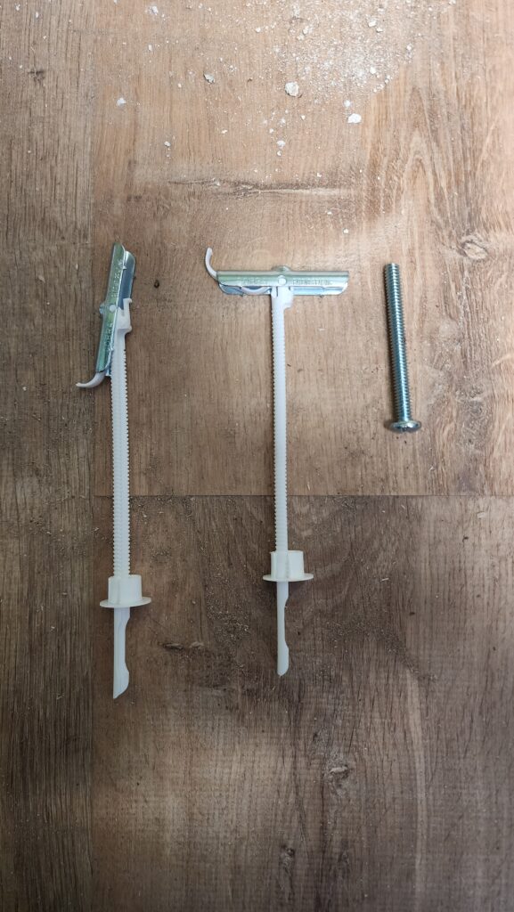
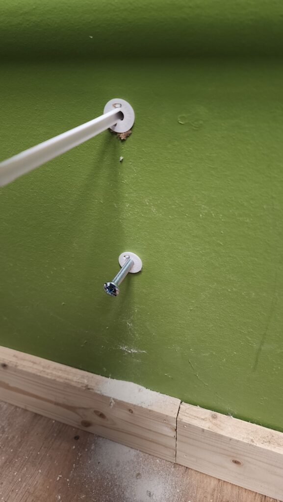
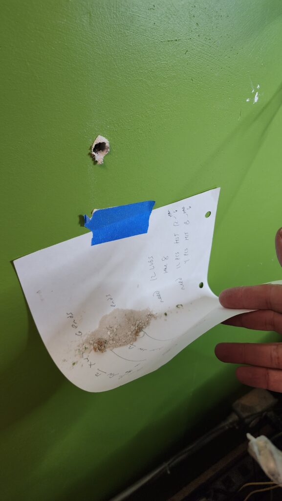
First, drill a hole. Then tip the metal bit back and insert into the wall. Pull it back toward you with the plastic lead to flip the metal bit against the back of the wall. Now cinch the round bushing down the plastic lead until it seats in the hole in the wall. Snap off the plastic lead. What makes this so special? Well, unlike nearly every other wall anchor, what’s left is a place you can set a machine screw and most importantly, you can remove the screw without losing the anchor. A traditional molly bolt gets lost if you remove the screw. Doing it this way means I can install a single anchor, remove the screw, put whatever it is meant to mount to the wall in place, install the screw, ensure the item is level, then while securely registered to that first screw, the other mounting holes can be marked with an awl or a sharpie. Next I’ll undo that first screw and dismount the item. The wall is now unobstructed and I know for sure the other holes I just marked are perfectly aligned with the first one. Drill and set those anchors. At this point I can install the item and all the screws. And if I need to dismount the item to rework it or whatever, I can do that easily without losing anchors in the wall. Like I said. These are magical and wondrous. The photo on the right is a handy tip for catching wallboard dust when drilling for wall anchors. No mess below, no vacuum required. Just hold the paper out a bit while drilling, then remove it carefully and pour the dust into the trash.
Okay – battery dolly is done. Bus bars moved to center and lowered for better dolly travel and reduced tripping hazard. Good. I still need to find a place to mount that second inverter, though, and you may have noticed this corner is really quite crowded.
The answer is to mount the second one above the first! Actually, the answer is to lower the first a bit, shift it to the left to make room for a future junction box, then mount the second one above it, so the high one isn’t way too high (and there’s room for the junction box).
It will be easier to install the high one first, so after measuring to ensure the lower one will have adequate clearance, I mark the wall for where the upper one goes. I can’t reach the studs to secure a mounting board where I need it, though, because the conduit for the light switch is in the way.
There’s really no practical way to move that without making an unnecessarily big fuss. It occurs to me, though, that the problem isn’t that the conduit is there. The problem is that I can’t install a plywood mounting board behind it, where I could then secure it to the stud there with lag bolts. The only reason I can’t get behind the conduit is that it’s basically flush to the wall. The only reason it’s flush to the wall is that this is where it has to be to meet the light switch device box. If I unscrew the box entirely and just let it hang there, I can simply flex the conduit a little by pulling it to the side and get the mounting boards installed and stud-secured where the conduit just was. That’s a good first step, but I need to put the lightswitch box back in place. Then insight strikes! The light switch doesn’t have to be flush to the wall. If I set it proud of the wall such that the newly installed mounting boards are simply behind it, then everybody works out! All I did was cut a piece of that same mounting board material and use that to shim the light switch with enough clearance that the mounting boards fit behind the conduit.
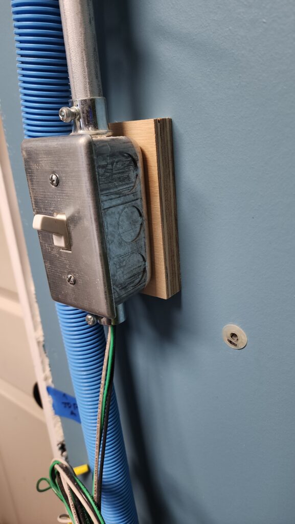
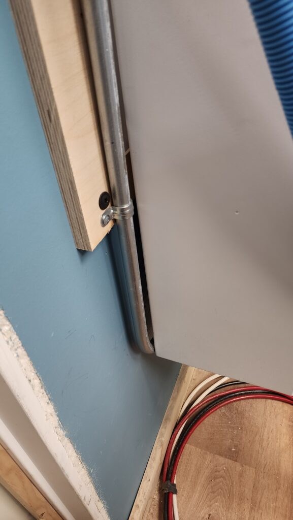
The conduit exiting the bottom of the switch box can flex a little more and sneak behind the repositioned lower inverter, so I don’t have to re-do the conduit at all, just flex it a smidge. Perfect. At least that part was easy and I get to keep some of my old work. I’m jumping ahead a little bit in the story here, but these two pictures went together nicely, so there ya go.
Back to that upper inverter. Now that I have the mounting board secured to studs, I install the mounting plate that will hang the inverter. The board is anchored to studs, so I can mount the plate anywhere on the board and know it will be secure. Imagine my disappointment when one of the lag bolts literally shears off as I drive it in. This is only 3/4″ plywood. It’s not like I was driving a 4″ screw through hard maple without a pilot hole. So it goes. Maybe these bolts don’t take kindly to being driven with an impact driver, even though impact drivers are magical. There are plenty of other suitable mounting holes, so I just find another in the area and use that.
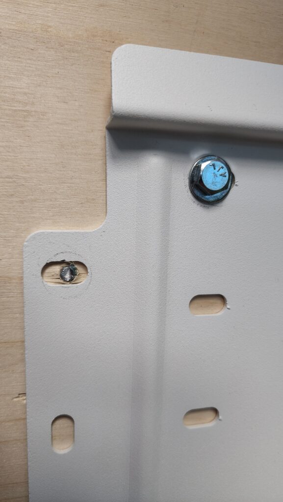
Plate installed, now I have a much more difficult problem. I have a 130# big metal box that needs to be hung on it, approximately 48″ from the floor. I try to simply lift it up into place, and while I am plenty strong enough to lift 130#, what I can’t do is get under it and shoulder press it into place without it toppling on my head. That is definitely not my desired outcome. I can’t get it high enough from a dead-lift position, either. There’s no room in here for a hoist, even if I had one (or built a gantry to use my block-and-tackle to do it). Crap.
It dawns on me to just grab a step ladder and walk it up. I only need it to be about 12″ higher than my natural carry position for it would be. If I were two steps up a step ladder, that would do it! I grab my short step ladder, put it in place, once again (after several attempts at manhandling it into position already, so I’m quite fatigued at this point) lift it off the work table and take a step onto the ladder. The ladder doesn’t break, but it wants to, and I can tell. I immediately step off and put the big heavy box once again on the work table. Right. The ladder is rated for 300#. I weigh 250. The box weighs 130. That’s 380. More than 25% overload for that poor step ladder. I don’t dare take two steps on it. Crap. What have I got that can take like 400 pounds of load that I can stand on to get 12 inches more height?
Answer: a few concrete blocks fashioned into a two step staircase.
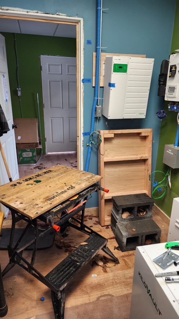
The inverter is shown here installed. It had been on the temporary work table (foreground). The wooden thing against the wall is the battery dolly before the batteries were on it (I’m not telling this story strictly in chronological order), in place to be somwhere I can rest the 130# inverter immediately if I need to, without having to maneuver it back to the work table.
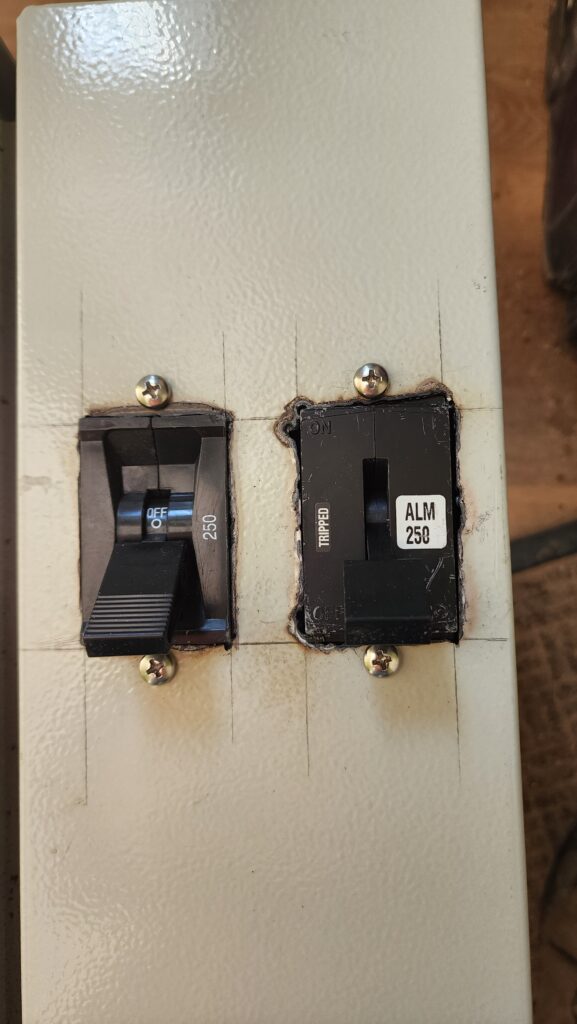
The next thing I need is to connect both inverters to the battery bank, each via a 250A circuit breaker. These things are kind of massive and the commercially available housings I could find that would accommodate more than one at a time were likewise massive. I don’t have a lot of space to spend on housings, so I needed a compact solution. I was not able to find anything off the shelf that would get it done. Time to fabricate my own solution, then. Wouldn’t be the first time (nor the last, I’m sure). The thing is, the breakers are big and the tightening torques are high, so the box they’re mounted in has to itself be pretty beefy. Steel, no question, and more than token sheet metal. I can find such boxes for sale, but how am I going to cut tidy rectangular holes in something like that? I don’t have confidence that my jig saw is up to that kind of heavy work. A friend suggests using a plasma cutter.
It turns out one can acquire a small scale one for a very reasonable price. Of course, I have zero experience with such a thing, but hey, time to get a new tool and learn some things. I’ll need some new PPE, too. Time to go shopping!
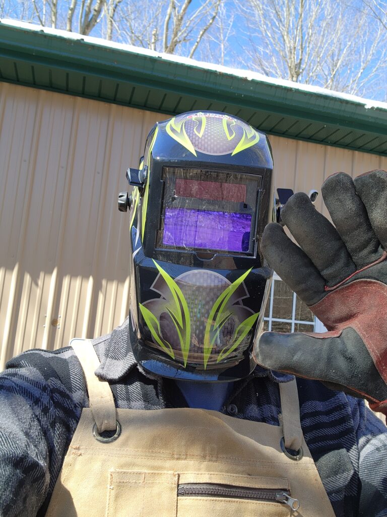
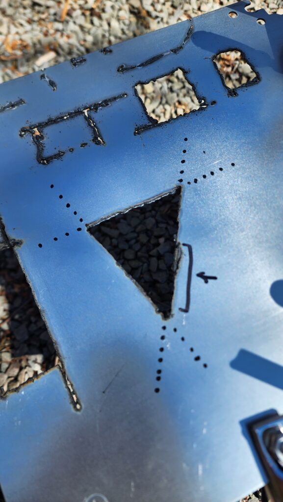
My leather apron I already had for the lathe and the welder’s gloves I actually use for fire tending, so I had a fair bit of the kit already. The auto-darkening helmet was the only thing I needed that I didn’t have. I’d have preferred one with fewer random graphics, but that’s what was available and I didn’t really care that much. Before going to town on my steel box, I spent some time getting to know the tool and how it cuts. It’s not a precision instrument, but with a steady hand, one can get decently accurate results with practice.
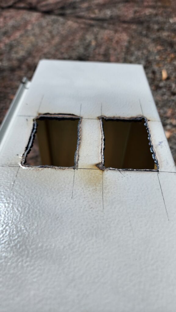
These holes aren’t beautiful, but they’re not terrible for a beginner and more importantly, they achieved the desired goal: mounting two 250A breakers side by side.
Now just wire them up…
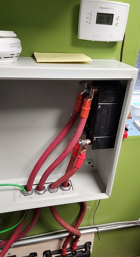
Those tidy holes in the bottom I had to drill, too. The box had nothing pre-drilled. Okay! 4/0 wires from the bus bars to the breakers to the inverters, done! Of course I had to cut that 1/2″ thick wire and crimp on those lug ends, too. All part of the job. I already had tools for that. I’ve been working on and developing this system for a while now…
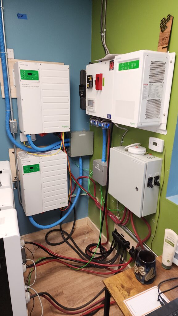
Inverters mounted. Power supply and breakers in place. New load center is wired up. What’s left? Configuring the inverters for cooperative mode, calibrating them, and connecting their outputs together. Still a bit of work to go.
There is no such thing as a ready-made junction box for what I want to do, so once again I buy a blank box and need to modify it to suit. This is that box, with the three AC wires (black, red, white) from the two inverters coming together and then their combined output heading to the load center on the thicker wires that exit through the lower conduit on the left wall.
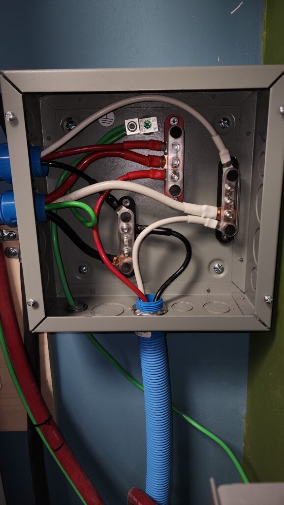
Those stud bus bars were purchased separately and of course I had to drill the box to accept them. No big deal to do that, but the box isn’t that thick and the stock screws I had were either too short or too long. Sticking out the back isn’t a big deal unless you want to mount the box flush to the wall, in which case sticking out more than a little bit past the mounting bosses becomes a problem (left).
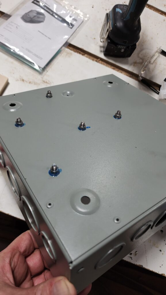
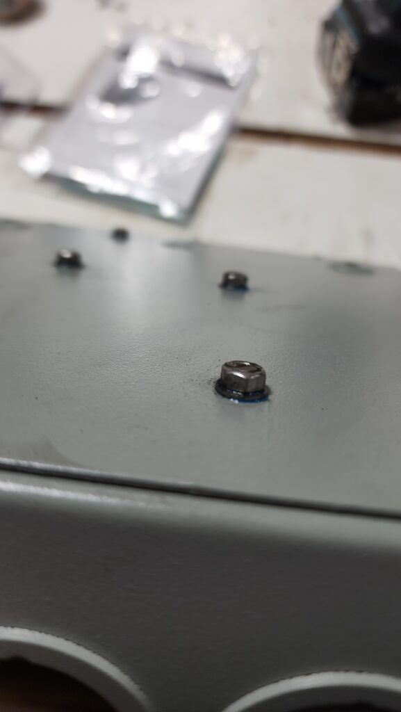
The answer is to grind off the screw stubs after installation (right). Makes a mess and is noisy, but gets it done, leaving only modest protrusions on the back. It’s good enough and mounts to the wall ok.
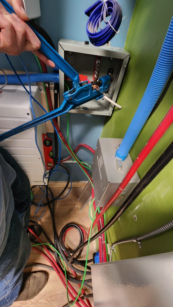
One thing that you might not have thought of is that the lug ends on all those wires had to be crimped on. But the all these wires need to be cut exactly to length after they were run, so they end up where they need to end up, without any extra. The #2 wires simply can’t bend in this tight space to accommodate any extra and the #6 wires that go to the inverters aren’t much better. So once I know exactly how long these wires need to be — by installing them — I need to crimp on the ends while they are in place. That’s not the easy way, but it can be done.
Now that the AC outputs are connected together, the inverters need to be configured (easily done through the gateway device that presents a private web site for system monitoring and setup) and calibrated.
The system documentation said I needed this special tool to calibrate the systems to within 0.5V of each other. I bought the special PC-based tool for approximately $600. I didn’t love spending that kind of money to do a one-time job, but it’s a critical job and the documentation said this was how. Okay, then, so be it.
The tool’s own documentation, however, was terrible. The system documentation that said how to use the tool didn’t look like the screens the tool presented. The installation of the tool’s software didn’t flow as expected, either. Not a great start. I was trawling the internet looking for answers when I stumbled on something that hinted the calibration I needed to do could be performed via the gateway I already had. Since the tool was giving me such a hard time, I decided to look into it. Indeed, my gateway had access to the necessary setting. Sadly, the tool was non-returnable since I had opened it… $600 wasted. I was not delighted by this. If only I had known I didn’t need the tool before I opened it… but alas, no.
I measured both inverters’ output to determine what calibration was necessary. It turns out they were already within 0.1V of each other — well within the calibration target of 0.5V — so after all that, I didn’t need to calibrate them at all, using the gateway or the tool. I was not delighted by this, either. But I was pleased that they were ready to go.
The real test, of course, is to actually run them under load and see that they are sharing the burden equally. These things can each deliver 12kW, so if they are doing it wrong, bad things will happen. This is a time for safety glasses, leather gloves (to quickly turn off something electrified/on fire), and to have the fire extinguisher nearby.
And that’s exactly what I did.
It works! My two most taxing machines, the new dust collector and the old table saw, start up promptly and reliably. When standing by the inverters, the machine startups no longer cause them audible strain. I think it’s cured! Time will tell, of course, but it sure looks like I’ve got it.
Shown below, the two inverters sharing a load, each reporting 0.38 kW of delivered power. Click to zoom.
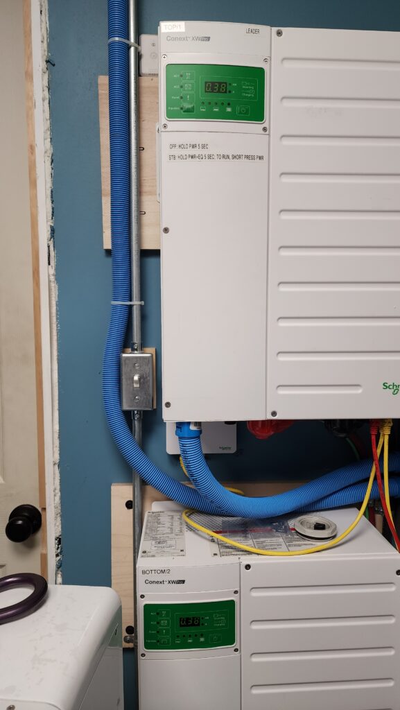
They can differ by up to 10% or so, but that’s fine. The power reporting is not a precise measurement in the first place, measurements aren’t taken at exactly the same time per each so may represent different points during a variable load, and the fact that they are not absolutely exactly the same output voltage means they may be a little uneven. All of this is okay. The fact that they are working together nicely to supply my heavy machines is a win.
Now everything is back in place and my office is no longer a construction zone. One of these days I’ll build a housing for that heater…
The other big project is getting the bee yard ready. The honeybee starter colonies will be ready for pickup in just a few days after the date of this post. I’ve been working hard getting the electric fence ready, among other things.
Last I spoke of it, I had run some conduit from the house to the bee yard. It was going to be a major bother to bury it all, given the condition of the soil… and by that I mean:


…but some of the run really would be a tripping hazard, so I spent some effort on just those parts.
Right next to the house… (you can see the tail of the conduit snaking away in the background)
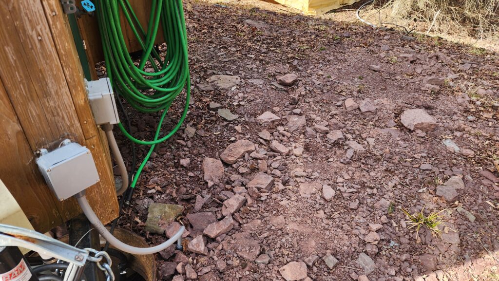
and past the sawmill, where I’d be coming and going with logs…
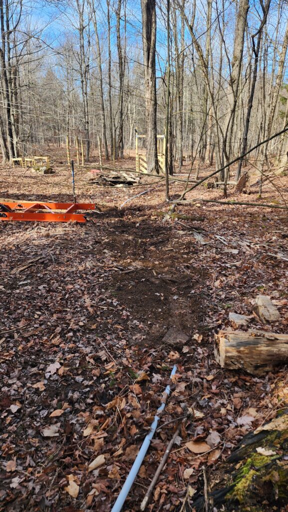
and right next to the bee yard fence, too, so it doesn’t trip me up while I am walking around there.
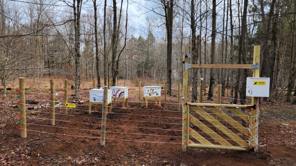
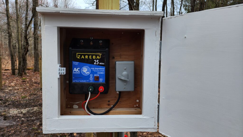
The white box contains the fence energizer, which, while it sure looks like it’s built for exposure, came with the instructions to protect it.
And you see that light brown stuff all over the bee yard floor in the prior picture? That’s peat moss. The answer to “why” is that all my first batch of grass seed was either eaten by birds or washed away. The peat moss covers the second application of grass seed, in hopes of hiding it from my avian neighbors long enough that it germinates and ceases to be bird food. Why do I need grass seed? This is why:
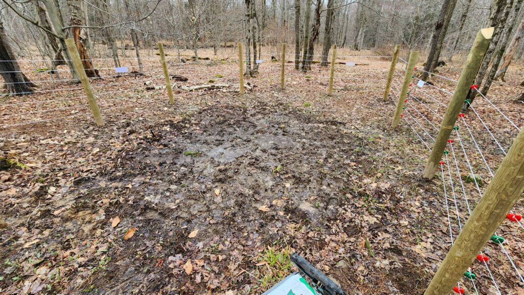
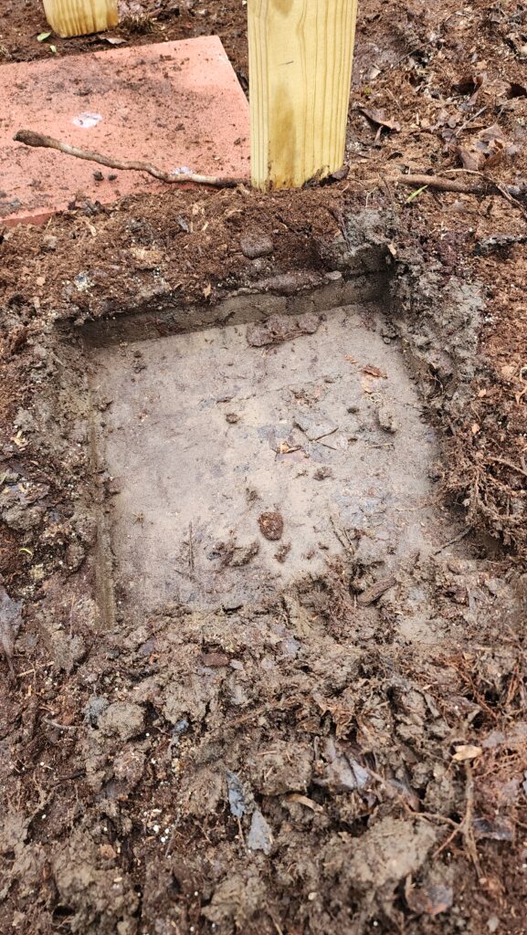
Without grass, the bee yard is a bit of a mud pit. And because it is so soggy, the hive stand legs are standing on 12″ square pavers, to spread the load out a bit. You can see the packed soggy clay here, where I removed the paver temporarily as I was working to get the hives level.
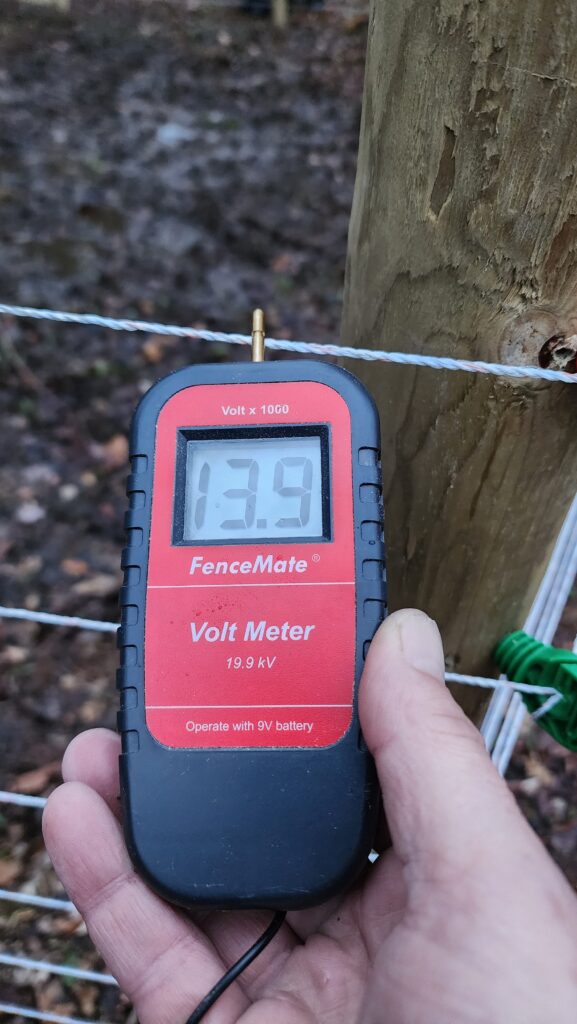
The electric fence is all in now, as you saw. And it’s ready for bear at nearly 14,000 volts.
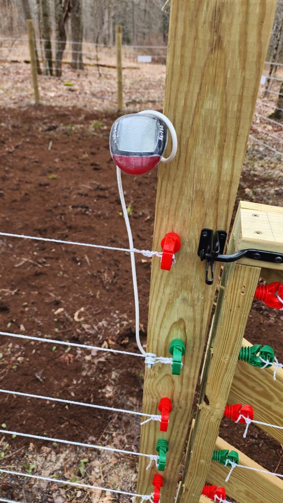
The red lamp detects the electric field from the top wire and flashes to tell me the fence is live. I can see it from the house, so a quick glance out the window is all I need to assure myself the bee yard protection is still in force.
The gate is designed to resist climbing – and if a bear gets close enough to climb it, the bear’s belly is close enough to touch the energized wires for a shock of discouragement.
The seconnd-to-last bit of preparation of the bee yard is installing the hive scales and the temperature/humidity sensors in the hive boxes. Here’s a view of the scale. It, along with the other sensors, will send their data to a wifi gateway which will transmit it up to the cloud where I can monitor the productivity, health, and environment of the hives non-intrusively.
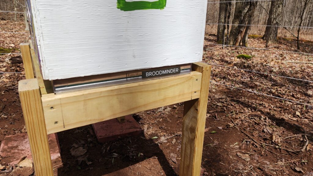
The cloud service will also draw inferences based on these measurements to determine overall colony health and will even send me email alerts if conditions warrant attention!
Installing the scale should have been as easy as lifting up the hive and setting it back down on the scale. But no, the bottom of the scale was about 2.5″ wide and the hive stand had only the 1.5″ edge of a 2×4 at that location — not sufficient for the scale. Some field modification was necessary to accommmodate it.
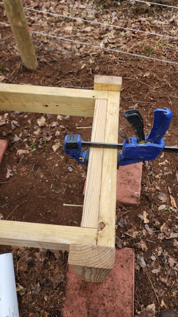
Not a big deal to double the thickness here – especially now that my wood shop’s dust collection system starts up reliably!
The very last thing I need to do is prepare some frame adaptors. The colonies will arrive on Langstroth Deep frames, but my hives are Layens style, which has a different frame size. To install the colony frames in my hives, I will need to build some special carrier frames. This isn’t a big deal, but they definitely need to be ready to go when the colonies arrive next weekend!
Still with me? I know this was a long one!
One last bit bit of agriculture/landscaping to report. Last year’s fruit trees are budding out nicely – 5 of the original 8. The two that were totally sogged out and moved mid-summer are showing no signs of life this spring. I fear they’re totally dead, but I’m going to give them until the summer to see if they somehow manage to recover. The ones that did well are coming back strong.
I also realized why that part of the land was getting so wet. There is actually a drainage path that empties right there. It’s nearly impossible to see in this photo, given last year’s fallen-over tall grass, but the solar arrays are up on a small hill, with a drainage channel in front of them, curving around behind them and to the left, where it becomes the channel next to the road where my frog friends live. The other end of that channel, though, used to end right where this new dark gash begins. Some rainwater would come this way and follow the path between the trees, seen here slightly darker green because it gets more water, flooding the lower area of that land. I have since cut this extension of the channel – seen here as fresh dirt – which I’m hoping will conduct the runoff past the trees and off into a different low spot, where I’m neither trying to regularly walk nor grow anything.
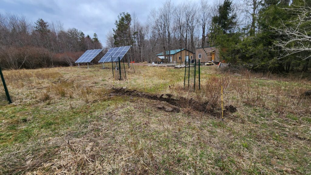
The end of this channel extension empties out onto a slope that flows down and toward the background of this scene, away from everything. I also used the turf I removed from the channel to form a berm on the lower (rear) side, to further encourage containment and guidance of rainwater.
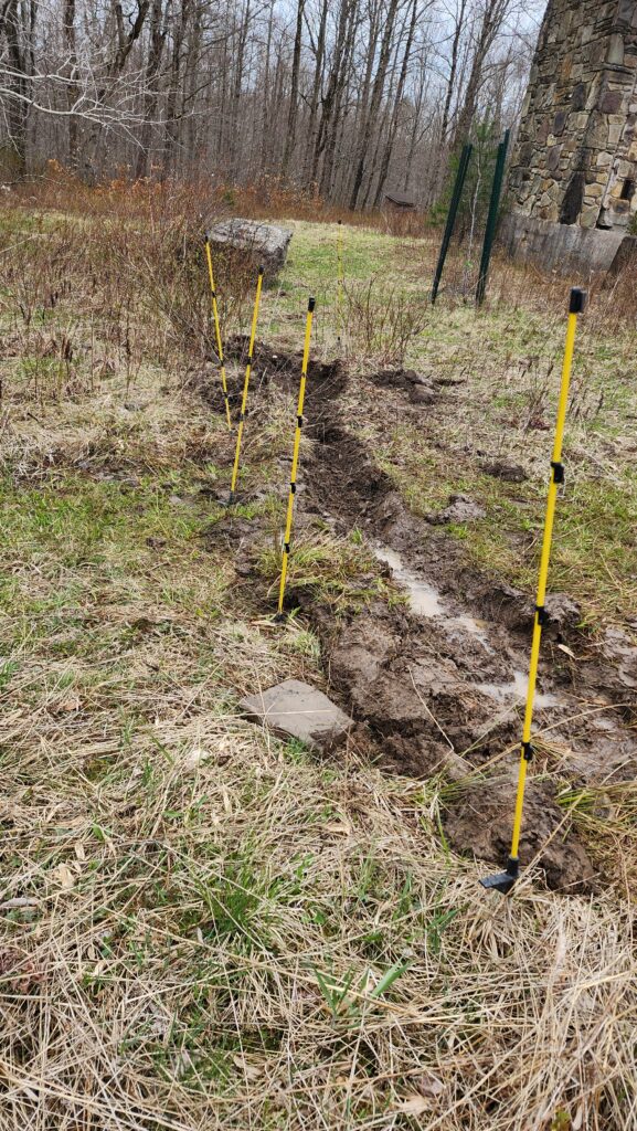
Will it work? Ask me after we’ve had some rain. But even now, clearly there’s moisture to be found in the land, as it is filling the channel with residual water already.