When we last left our hero, the W.O.G. wood stove needed just a couple of things before it was ready to go – being affixed securely to the floor and some sealant between the flue collar and the flue.
The stove had some pre-drilled holes in the pedestal for the floor-attachment (see blue screw set in the hole to identify it)
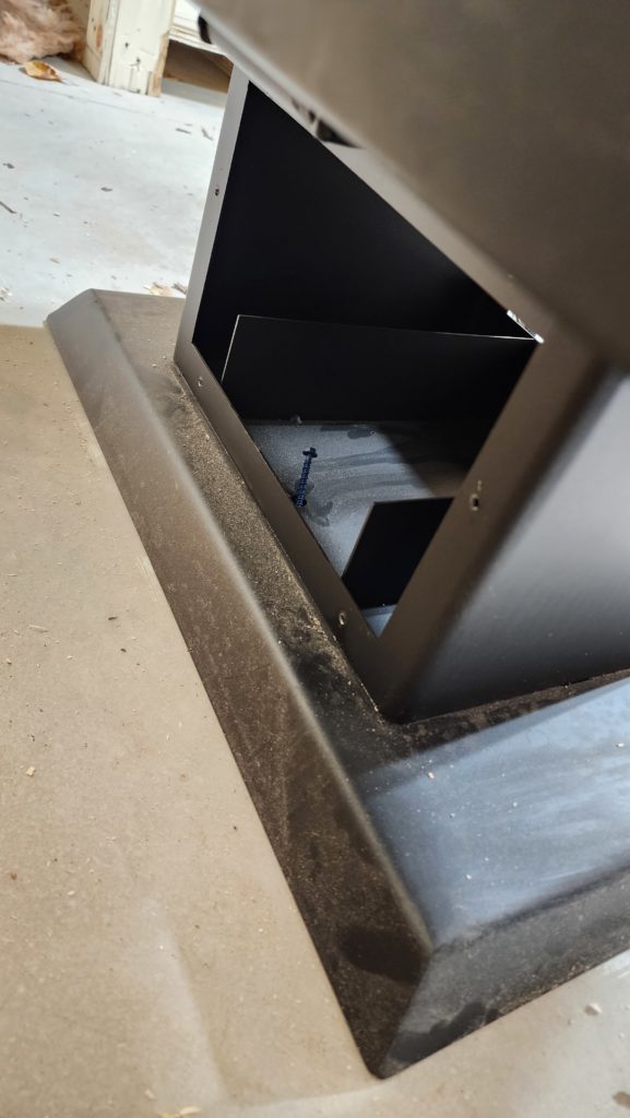
The thing is, that little compartment in the pedestal is too small for my hammer drill, so I can’t actually drill into the concrete, through that hole, to receive the screw! At this point, the flue is now built onto the stove, so there’s really no dismantling it without actually taking down THE WHOLE DAMNED THING, from chimney cap back to flue collar, because it’s all locked together and there’s no room to maneuver the intermediate parts. That’s just not gonna happen without a much stronger motivation than a difficult-to-drill screw. Time for Plan B.
Plan B is to drive some screws through the pedestal flange instead. It turns out the overhang of the stove body gets in the way of that, too, with respect to finding good clearance for my drill, but if I go in at an angle, at least it’s possible. Well, the cast iron base of the pedestal wasn’t especially hospitable to my drill at first, so it needed some persuasion.
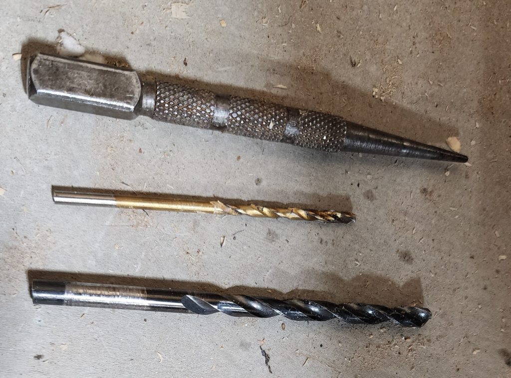
Persuasion comes in the form (from top) of a nail set (and hammer, not shown) to make a dimple in the metal to capture the tip of a drill bit. This is followed by the smaller drill bit to make a hole big enough to capture the tip of the larger drill bit. This is followed by the larger drill bit to make the clearance hole in the base. Only when all of this is done can I actually approach the concrete with the hammer drill, through the clearance hole, at an unseemly angle, but that’s the best I can do given the clearances available.
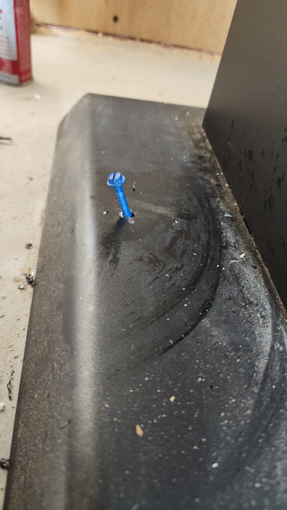
So okay, it gets done. One screw in the side, one in the front, repeated left and right. Now the stove is secure. Shmear a bit of sealant under the flue collar and it’s good to go!
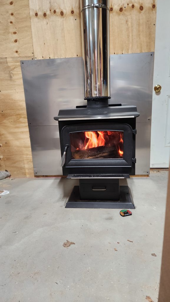
The test firing was a success, with one exception. The stove’s manual said to do a low fire first, let it cool, then do a low fire again, let it cool, then a high fire. The reason for this was “to cure the paint”. I had the stove thermometer (shown on the floor) on the top surface of the stove when I started this process. Then I realized — while the fire was burning — that it might interfere with the paint curing process and went to remove it. It turns out the magnet that holds the thermometer to the stove is pretty strong and going after it with fireproof-gloved hands was clumsy at best. I wound up rubbing the surface of the stove in a few places and behold, the paint was a little bit liquefied at that point, so I spoiled the paint job a bit. You can see the evidence of that on the top, in front of the flue. Those shiny parts are not reflections. They’re spots where I disturbed the liquefied paint at a critical time. Oh, well. At least this is a workshop stove and not a showpiece living room stove. No need for it to remain pretty. Still, a shame that it happened.
Speaking of getting warmer, that’s one thing my water heater stopped doing recently! It wasn’t even trying – no spark, no whirr, no nothing. It has been exhibiting some reliability issues over the last few months but then it stopped entirely. This is an on-demand water heater, so it’s a bit more complex than models with tanks. The whole thing would be like $600 to replace, to I was keen to attempt to repair it, if possible. Lucky for me, I was able to locate a technician’s service manual for it that included diagnostics. It didn’t take long to identify the flow sensor — the thing that tells the water heater that somebody is calling for hot water — as the culprit. I was able to locate a replacement part and get it delivered for $40. More than I thought something like this should cost, but definitely more appealing than a whole new heater!
Now comes the tricky bit: replacing the sensor. Let’s start with a quick tour of the location.
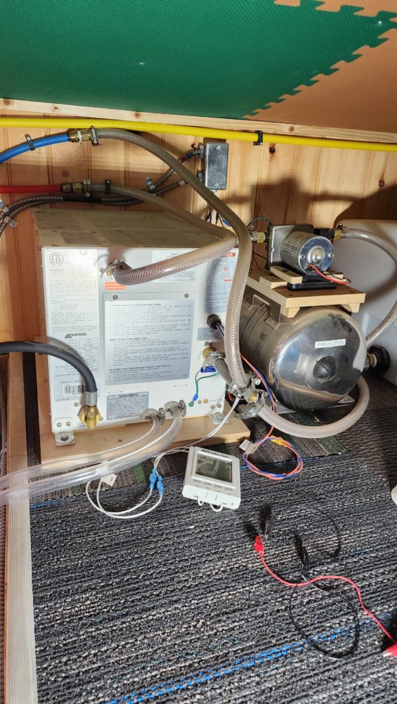
The heater is the white box. You’ll notice there’s pretty much no room to the right before the pressure pump and accumulator (silver tank). The silver strip to the left is the edging of the utility loft — no room that way, either, before it drops off 7ft to the main level. Now, where is that flow sensor?
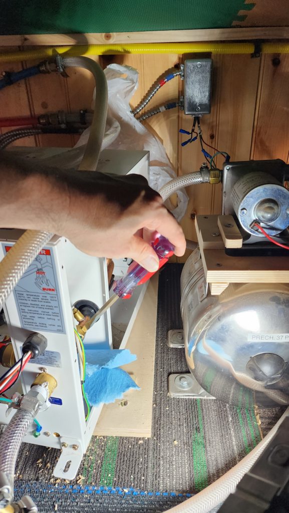
It’s here. I’m touching it with the screw driver. Not exactly a lot of room to work. Note the green ceiling tile. This is the low-headroom side of the loft. There is just no way I’m going to be able to work on this in situ. Sigh. Okay, then, drain and disconnect all the things.
While thinking about the flow sensor failure, it occurs to me that for the first 6 months or so – maybe 9 – I had been experiencing a considerable amount of sediment in the water. Then I installed a filter, but before that, there was quite a bit that flowed through the system. I suspected the sediment fouled the flow sensor. I don’t know why it would work some times and not other times, ultimately failing and staying failed, but that’s how it was. Maybe the sediment collected in the sensor would move around a little, maybe certain conditions caused it to stiffen. I just don’t know. What I do know is that the sensor failed and so I had to replace it.
This is it. Note all the red gunk.
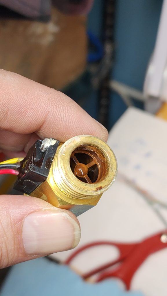
I was able to stick a probe inside and twiddle the thing that needs to move, so I don’t think it was a seized rotor. Maybe the sediment got into the sensing apparatus itself? I don’t know and the sensor defied my reasonable attempts to remove the flow cell. There are a couple of screws on the sensor module that attach it to the brass flow body — I may remove those later to look inside, but at that point, chances are I’ll have destroyed it. I was thinking maybe instead I could clean it with an alcohol wash and keep it as a spare. . . in which case, destroying it is not the right move. I’ll decide later.
Here’s the sensor in place, before removal.
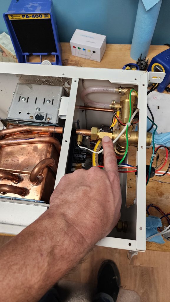
I must first loosen the compression nut on the left, then unscrew the brass flow body from the inlet fitting on the right, all the while being mindful not to put torque on delicate things, like the copper tubing that goes to the heat exchanger. A pair of wrenches and some finesse gets it done. This would not have been possible up in the loft. Much of a bother as it was to un-install the heater and bring it down to a work bench, it was such the right thing to do.
New sensor in place.
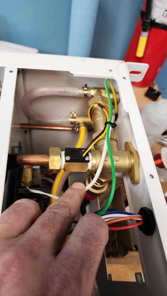
It looks rather a lot like the old one — rightly so — though screwing it in left it in a slightly different orientation. No matter. I also added thread seal tape (white) to it while I was at it, for good measure. I do NOT want to have to dismount this thing again because I later found a leak.
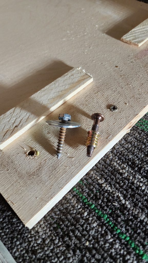
But speaking of dismounting, I did realize that I had use wood screws to anchor the heater in place and I already knew this was the second time I removed it since placing it, and we all know wood screws don’t really like going out and back in more than once. I replaced the wood screws with machine screws and insert nuts so if I had to do this again, I wouldn’t lose the ability to secure the unit back in place after.
Now I set some paper towels (blue) around to catch any drips and I turn the water pressure back on and let it flow a bit to ensure all the lines are primed. Now I wait a few minutes to see if any drips emerge (or worse).
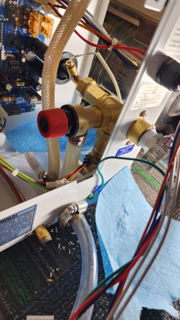
Happily, the only drip is at a hose fitting outside the machine. I cinch the hose clamp a little tighter and all is well. Time to button up the machine and see if it makes hot.
Nope. Time to drive the machine back into place and somehow manage to mate the exhaust manifold with the back of the heater unit. Except I can’t see back there.
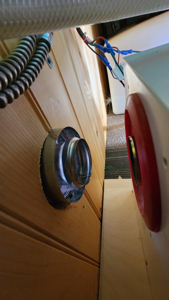
These are the parts that need to mate. With a significant gap, I could get my phone back there to take this picture, but there was no way I could get a live line of sight, even with a mirror, to get this done. As it happens, the unit needs to be lifted just a tiny bit to mate with the exhaust pipe, which will then bend downward slightly under tension. But how to get it there? Normally, the exhaust pipe is installed last, with the heater already in place, so the whole thing can be guided easily by sighting down the exhaust pipe from the outside. But it’s already installed and sealed to the house. I don’t want to undo that. I want to gently back the heater onto the exhaust pipe, instead. Ah, yes! I remember now. The left side of the heater housing does grant some visibility to this connection. That should do it.
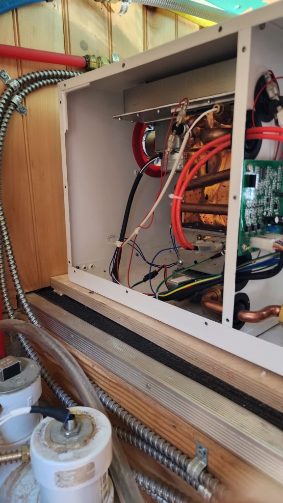
And indeed it does. Success. Now, about that water. Does it get hot now?
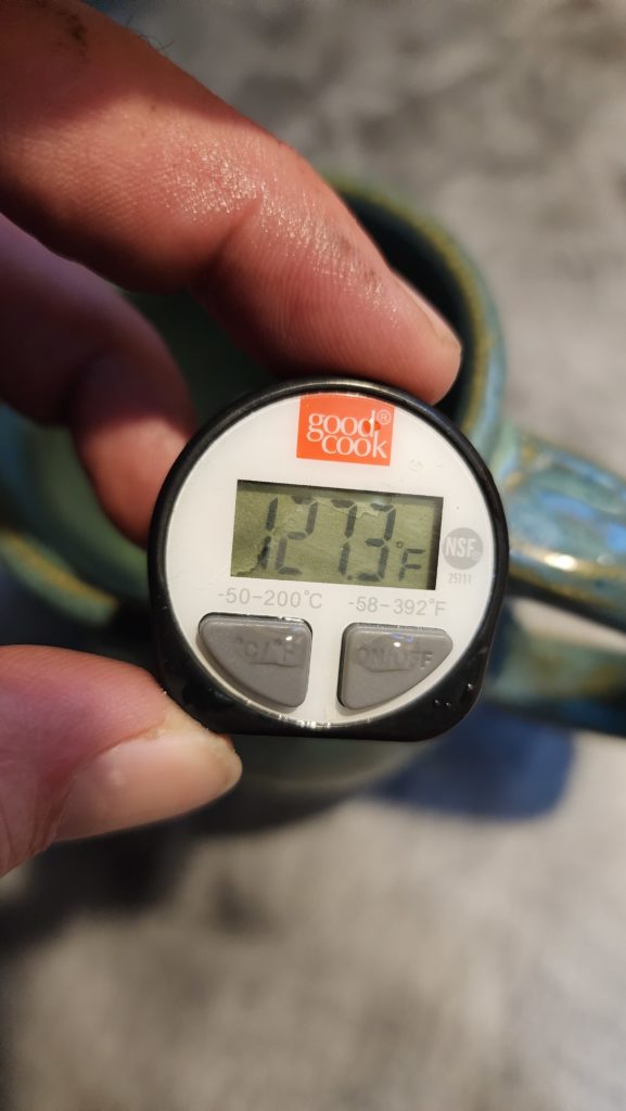
Indeed it do! Mission accomplished.
It was good weather recently, so I took the opportunity to do a little outside electrical work. You probably won’t remember, but it turns out my solar array can generate more power than I expected it to. Ordinarily, that’s a good thing, but in my case, not so much because I had some wire rated for 30 amps that was being exposed to more like 40 amps at peak times with the solar. The wire didn’t suffer, but it did get much hotter than makes me happy. Also, all that heat is energy that isn’t making it to my battery system! The good news is that the long haul from the solar array to the W.O.G.’s power center is very heavy gauge, totally happy with the larger current. It was the interconnect wire that was too small. Or, rather, it was sized appropriate to the current I expected, but undersized given the current I observed. To mitigate this, I set my system to limit the power to a safe level. But what I really wanted was to upgrade the interconnect wire to handle the larger current and remove the limit. This would let me safely collect full power under all circumstances. This was the day to do the outside part of that upgrade for the W.O.G. array. Here’s a snapshot of the old wire (white with yellow tag) and new (black).
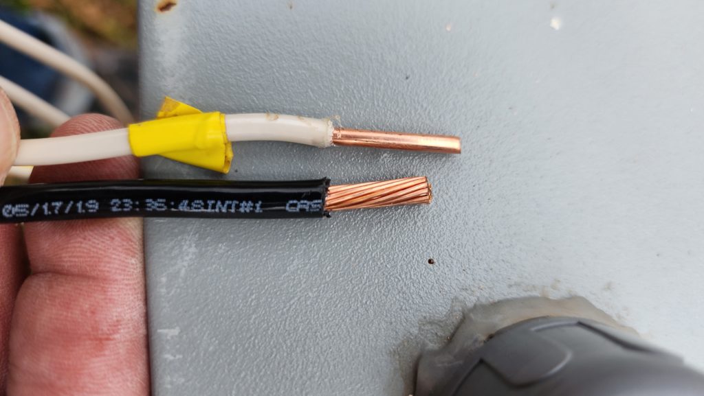
You’ll see that the black wire is about 30% bigger. That makes all the difference. It’s also stranded wire, vs solid, which makes it easier to use because it flexes more easily.
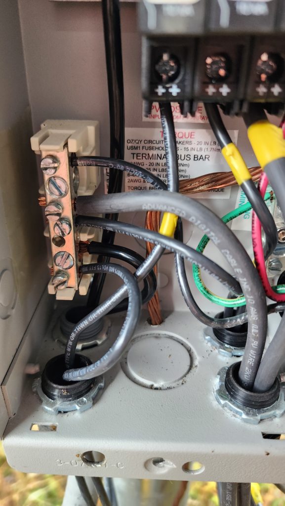
And of course I was double careful to tighten the screws on the bus bar good and tight. And come back in an hour and tighten them again, if needs be, before closing it up. This is the place where a loose screw caused some minor melting last year!
I still need to do the corresponding operation on the interconnect wire in the office, but that will wait for a little while yet. I ordered one more battery module which will require a bit of rework in the power corner of the office. I’ll take care of all that stuff at once, during installation.
And speaking of good weather, there’s not much more of it left before winter sets in for real! Even though the place to put the boards to dry hasn’t been built yet (soon — needed to have the stove installed first, so I could build while it was cold), I wanted to get started milling the logs from last year, which were already getting a bit old for cutting.
Indeed, some of them already had visitors…
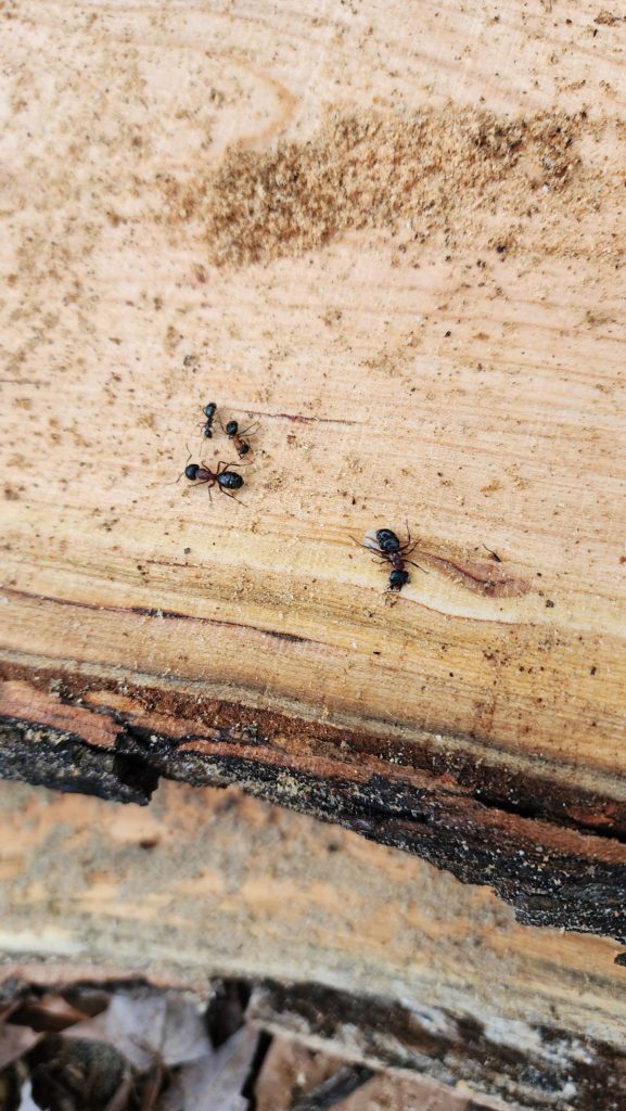
These were dealt with harshly. I don’t enjoy killing creatures, but these boards were about to go inside the W.O.G. and therefore needed to be free of unauthorized life forms. I flooded the passages with alcohol, which seemed to do a fine job of driving out some of the ants and killing the rest of them. I am keeping close watch on those boards.
Meanwhile, many of the other boards had some interesting features in them. These probably represent disease or necrosis of some kind, but even so, they made for some interesting figure. The one on the right, especially (click for full view), was compelling. I have two boards that look like this. I think they’d make great doors on a small cabinet.
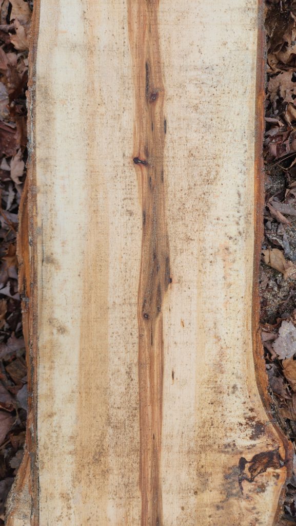
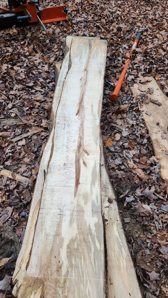
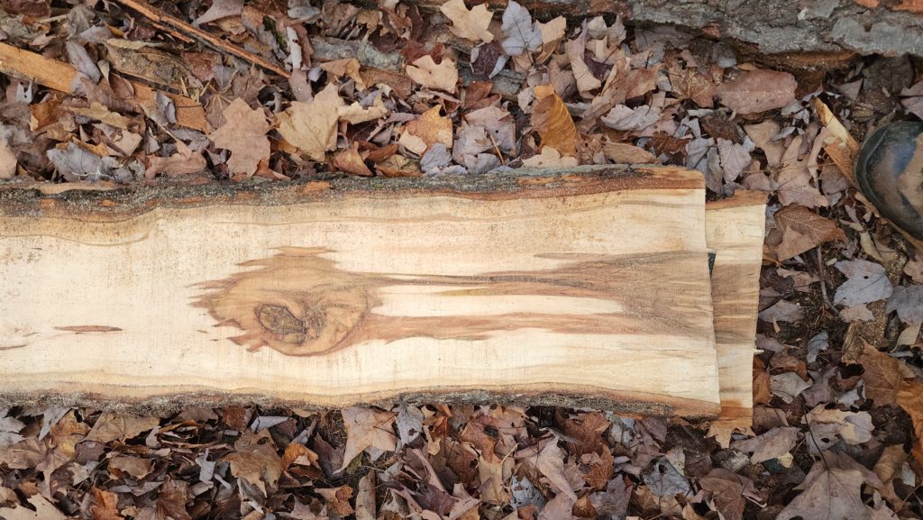
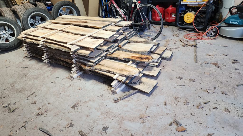
The day’s harvest, temporarily living in the garage until I get the drying hallway done, which is next on my construction agenda. Dark spots are where it’s still wet from the alcohol flush.
Lastly, I leave you with this dead Ash tree, as it begins to lose its bark, looking a bit muppet-ish…
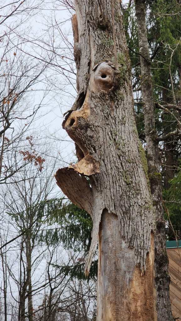
This tree will be a guest of the sawmill next spring, most likely.