Things have been pretty quiet here in TINBIDIA over the last several weeks. Some vacation, some socializing, some settling in to my new job, wildflowers nicely in bloom, some more of the same in the W.O.G.: walls and insulation work. Nothing new/interesting worth writing about, so I didn’t.
There have been some developments lately, though, so let’s have at it, eh?
First of all, autumn has arrived here in the mountains. We’re still getting some warm days, but nights are 40s-50s mostly, and some days don’t break 70. Time for me to get my winter checklist together and get on with it. On that list are a woodstove for the W.O.G., cleaning the flue in the HomeBox proper, building a hutch for my cordwood (free stacking it last year was such a bother and I’d rather it have a roof and airflow than a tarp and mold/fungus), to name a few.
Back in April (it’s mid September now), I ordered a sawmill. Now, when most people think of a building. It turns out there are such things as portable sawmills, too. Personal sized ones. Just the thing for someone living in the forest who wants to be able to slice logs into boards for their woodworking habit. I bought one of those, a Woodmizer LX-55. It took quite a while for it to get manufactured and shipped, but it did, arriving a couple of weeks ago, looking like this:
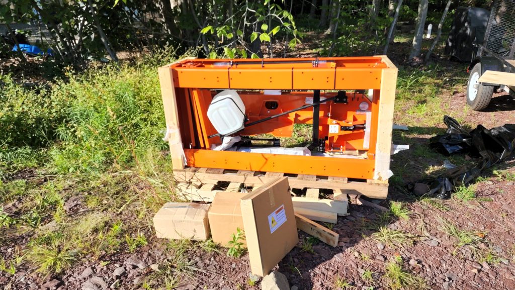
I was impressed with how they used the bed rails as structural elements in the crate. That was pretty clever. Somehow the entire machine fit in this crate (minus the engine, which was in a separate box).
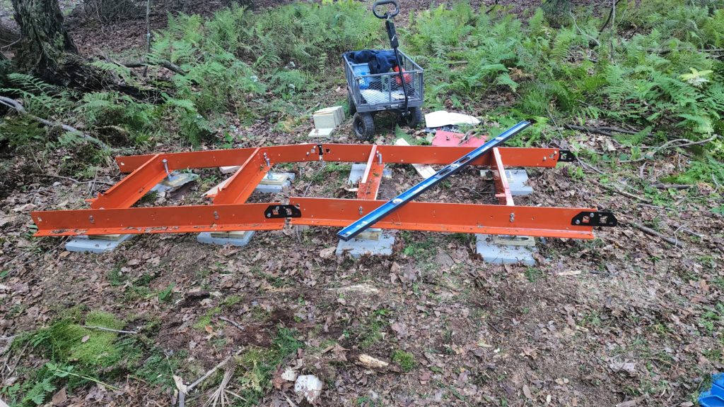
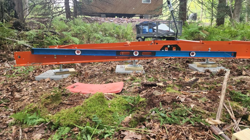
Step 1 is to assemble the rails on which the saw carriage travels. The rails have to be nice and level, nevermind that the ground is not. So I built it in sections, starting with the middle, making that level, then adding the front and back sections individually, bringing them up to meet the middle section, then making them level. That was quite effective but time-consuming because the ground, while it looked a little bit sloped, turned out to be a fair bit sloped, as evidenced by the departure of the rail from the projection of the level (blue) in the right photo.
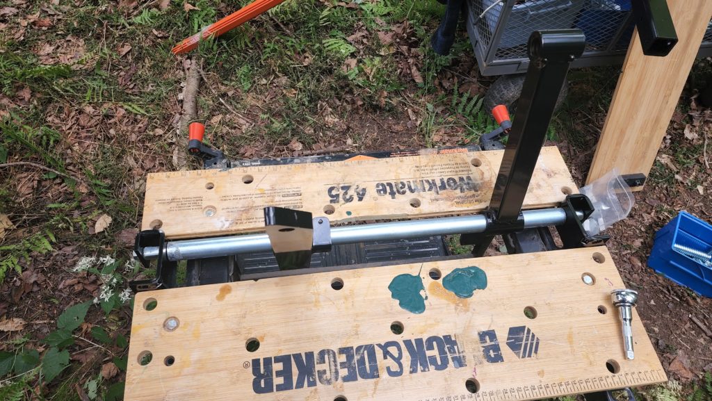
There were some other challenges, too, like how to tighten this shaft between these two brackets, while keeping the brackets perfectly aligned. My trusty B&D Workmate clamp table to the rescue! It could hold both bracket ends in place, with the heavy steel parts hanging off the shaft as they needed to be, while I tightened the bolts in the shaft ends securing it to the brackets. Sometimes, ya gotta get creative.
So I got the track all assembled (including these fixtures) and perfectly level… when I realized something critical. The track is not ambidextrous. There is a definite loading side and not-loading side. I had placed the track in such a way that I expected to load it from the operator’s left, but the machine is clearly designed to load from the operator’s right. Crap. Now I have a fully-assembled (probably about 200# of steel) track in the wrong place, perfectly level. Good luck was with me, however, in that I had a helper available that day who could just grab the other end of the track and help me relocate it as-built such that there was now room to do the loading from the other side.
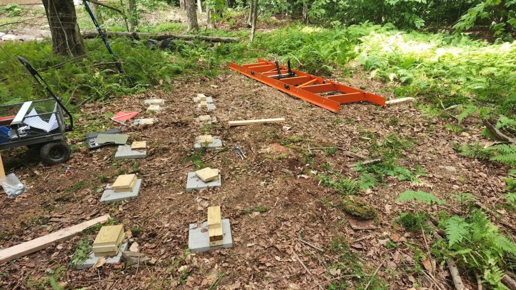
This did mean a new leveling job (after moving the concrete pads and pressure-treated shims) at the new site, but at least I didn’t have to disassemble the whole thing to move it (which might have been the case if I had to work solo).
Somewhat later in the assembly process, I discovered a problem. This is the sawhead carriage, flat on its back. See those blocky feet? Those are the rollers on which the whole thing rides along the rails. See the two bolts attaching the long square mast (black) to the roller feet? Yeah. There are two per foot. Except they only gave me two in total.
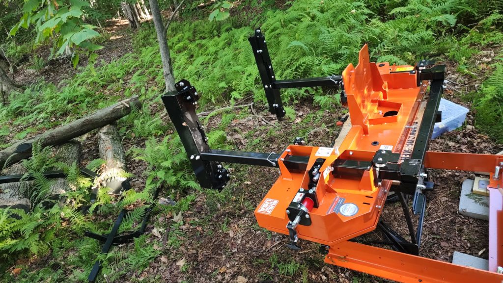
These are long, metric, carriage bolts. These are not available off the shelf at HD or Lowe’s, even the ones in town. I’m not so inclined to mail order two stupid bolts and I really want to move along with assembly anyhow. What to do? Well, it turns out there are identical bolts elsewhere in the machine. Specifically, they attach the cross-piece (black, horizontal, middle of frame) to the masts with the feet (pointing toward background). See the two pair of bolt ends to the left and right of the orange tracks? Yeah, those. They’re exactly the same as the bolts needed for the feet. But I can’t just take them out. These bolts have to be here, too.
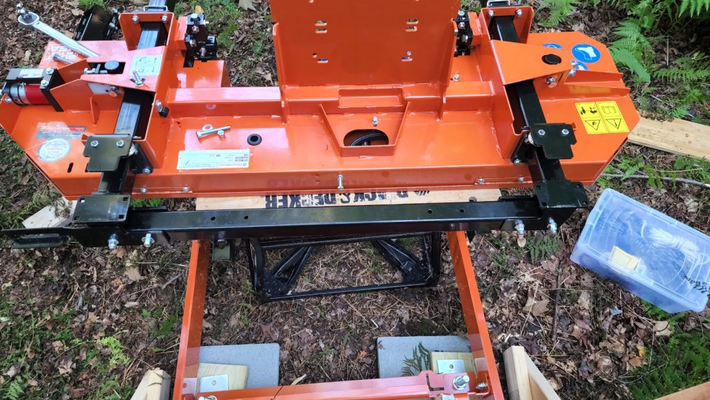
That’s true, but they don’t have to be EXACT FITS like the foot bolts do! These bolts here just hold the cross piece in place. I can take one of the two bolts from each side, leaving one to be the exact fit to hold the parts in place, and then substitute the closest SAE (inch sized) bolt for the second one, its job being simply to apply additional tension. Indeed, the two bolts are difficult to tell apart. SAE bolt is at the bottom. It’s very slightly smaller in length and diameter.
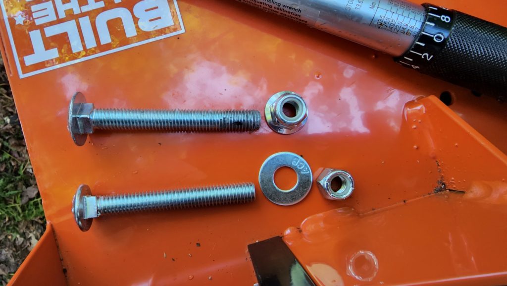
This substitution worked great and allowed me to proceed without further ado.
Now that the saw head is mostly assembled, and definitely has its roller feet attached with the proper bolts, it’s time to put it on the tracks. Except this thing is awkwardly sized and easily 200# or more in weight. I can lift a 200# when I have to, but finessing a 200# machine onto some tracks is another story. There’s no good place to grab it to get a good lift and anyhow, the job requires both lift and rotation, since the machine is on its back now and needs to be righted. I don’t want to set it in the dirt, potentially fouling or bending parts of the roller feet. So a solo lift seems unworkable. No helper available that day. What to do?
Gantry. I need a gantry. So I build a gantry. From the gantry, I hang my block-and-tackle, which gives me 3:1 or maybe 4:1 advantage, so I can lift the ~200# saw head and let it find its footing naturally if I rig it so this is possible, which I do, and it was.
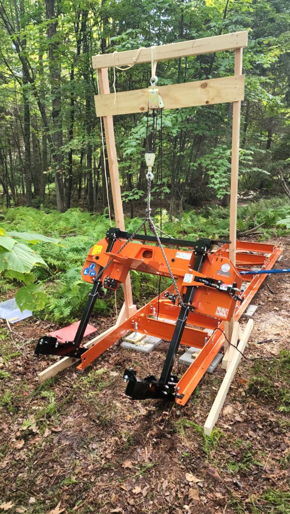
The feet did see some dirt, but at least they didn’t have to bear the weight of the whole machine into the dirt, just a little toe-digging-in. To keep the gantry from falling forward as it was lifting off-vertical, pulling the machine off the work table (since removed in this photo) and bringing it toward the track,. I extended the gantry’s own foot braces forward quite a bit, giving it some staying power against tipping over.
I did goof a little, though, in that the rope loops attaching the block-and-tackle to the gantry were a bit too slack to the point where with the thing fully retracted, the saw head was still not quite high enough!
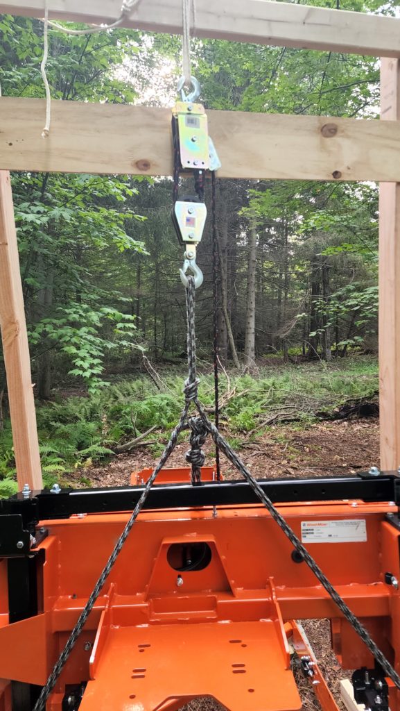
Those extra few inches of white rope at the top would have made the necessary difference in height, had I looped them tightly instead of like this. Ah, well. But now I’ve got this machine already suspended but a couple of inches too low to get it on the track. Crap. Now what? I don’t want to set it down (in the dirt) and landing it back on the work table seems unlikely to succeed. I refer you to the previous photo, showing the feet at an angle. I was able to swing the machine forward a bit such that the leading (lower) ends of the feet DID engage the track rails, which then meant I could finesse the machine vertical from there, with the gantry/block-and-tackle taking most of the weight, until I had it righted on the rails. Okay! Did it!
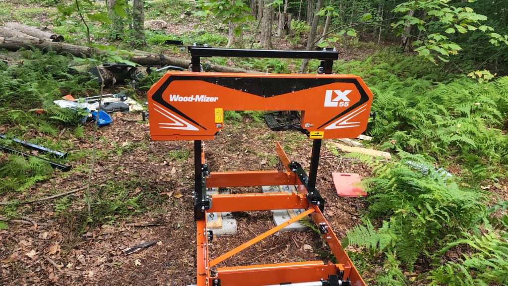
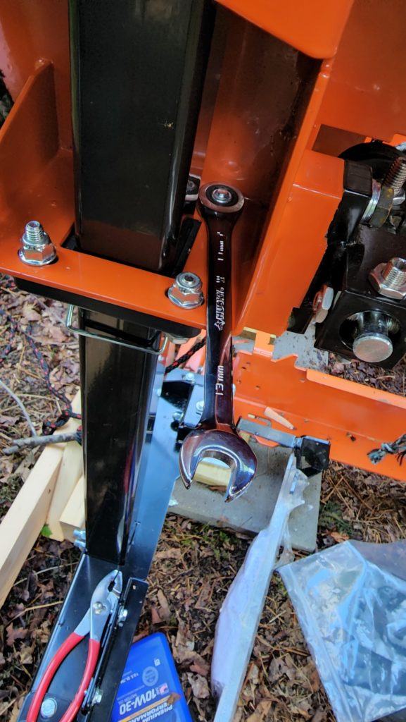
The rest of assembly went decently well, though occasionally there were some very tight quarters for working nuts and bolts. My ratchet-head (“gear”) crescent wrench set came in quite handy there.
Know what’s a challenge? Dropping a 1/4″ long black screw on the soft, leafy, forest floor. It looks big in the picture, but those marks are 1/32″ apart and there are only 8 of them along the length of the screw.
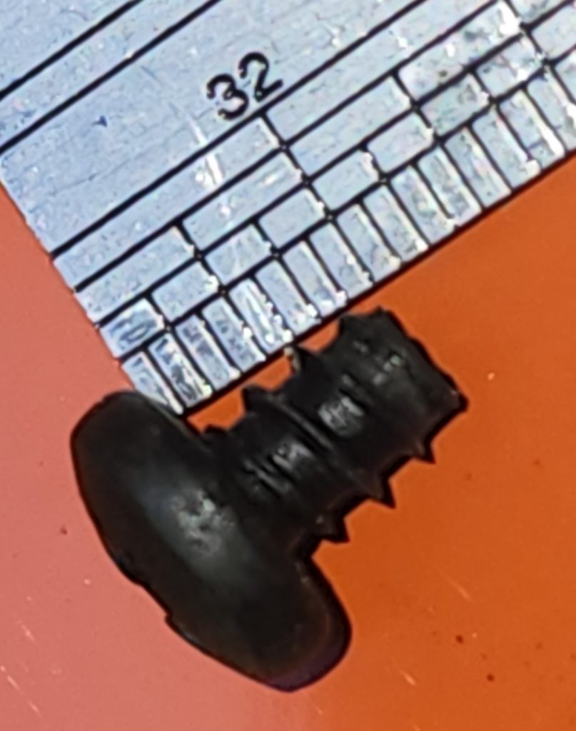
How DOES one find such a thing amidst leaves and twigs and moss in various states of decay and shades of brown and black? A magnet on a stick, that’s how! It took several tries, but eventually, the very satisfying *plink* sound of the screw being attracted to and landing on the magnet was heard. What else are magnets on sticks good for? Lots of fun stuff, though retrieval is definitely their primary mission. They’re also good at installing spacers in tight places.
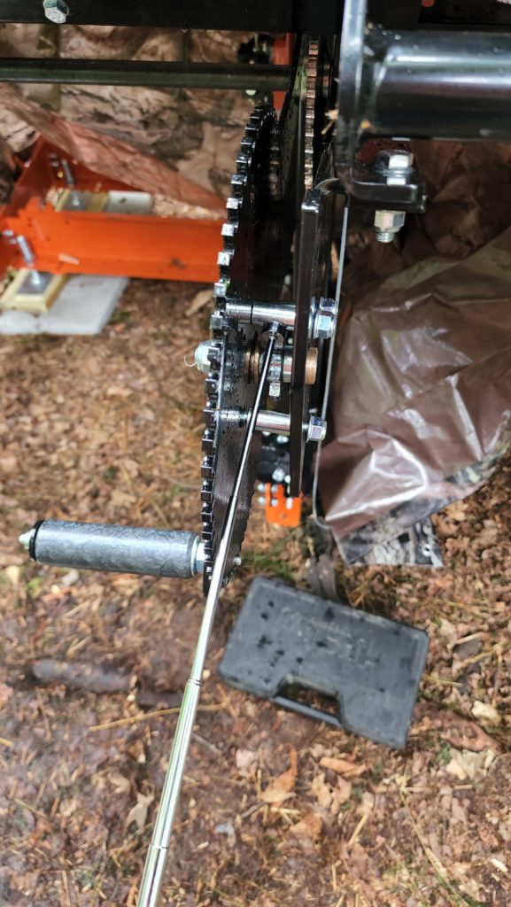
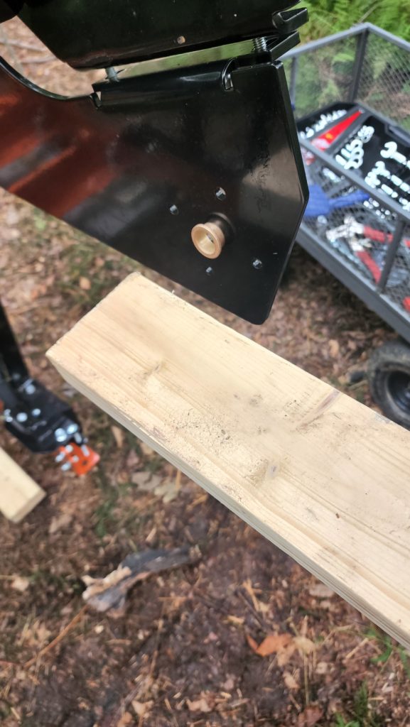
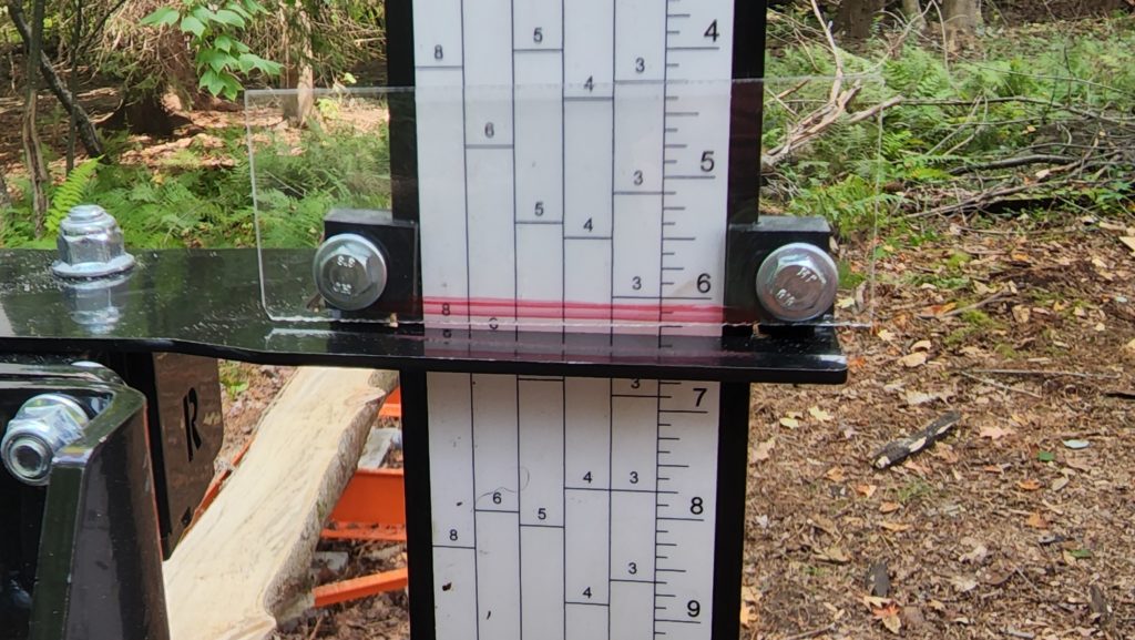
The very last of the assembly challenges was that the blade height gauge could not be adjusted far enough to tell the truth about the blade height. As designed, it was meant that the black bracket holding the gauge here was the place to read the gauge. But no, the adjustment available for the gauge scale wouldn’t allow getting the right number to align with the bracket. A secondary reading line had to be introduced. And so it was (red, on acrylic). Top of the red line is the true blade height.
And then, finally, it was time to cut some wood!
The first pass wasn’t too exciting – just skim enough off the top to make a flat surface. The first real board cut, though, was positively momentous and is captured in this video.
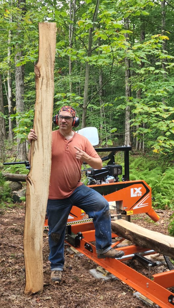
After cutting a few more slabs, I discovered a problem. The dust chute was going to hit an old stump (behind the foliage) as the carriage was lowered for cutting the last few boards from a log.
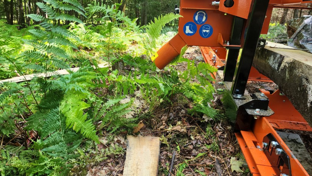
I also realized that some of my logs were too short for the spacing between the log braces! This one looks like it would just barely make it, but not safely.
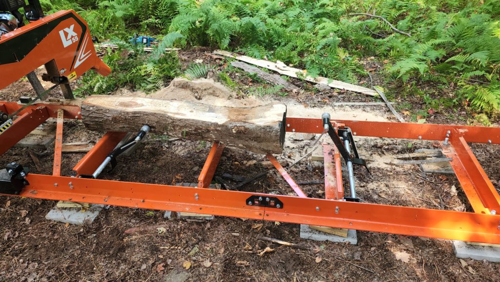
So I moved the braces closer together, swapping places with the diagonal brace… and cut a big notch in that old stump with my chainsaw, which in the photo below just looks like a pile of sawdust (from subsequent cutting operations of the mill) — but that sawdust cliff was solid stump before.
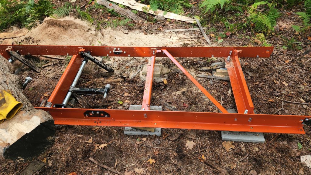
And that’s pretty much the mill story — it’s now ready to attack my pile of logs, though I need to make some place to put the cut logs to dry! I’ll find space in the workshop for that, though really, there is somewhere I have in mind to put them in there that just isn’t built yet. Hm. Maybe that get priority for what’s next to build in there!
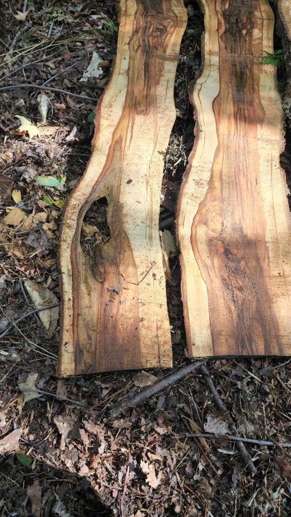
I did cut two test logs today. The first one, shown above. And another, which looks like it had some kind of infection/sickness affecting its heartwood. Some of it rotted out completely (note the window in the left slab!) That said, the discoloration was really quite striking. It cries out to be used as an accent panel, or maybe the sides of a Very Interesting Box, or some small cutting boards, to take advantage of the dramatic coloration. Even some injured wood (this) can find use. Some is likely too far gone to be useful, though there are some techniques involving epoxy filling that can take even the most derelict wood and make something interesting from it.
I promised you a gazebo, quite many words and pictures ago. I haven’t forgotten!
I haven’t actually BUILT a gazebo. What I have done, though, is started a design for one. This design uses timber framing techniques — pegged mortise-and-tenon joinery, chiefly. No metal fasteners (screws, bolts, nails) in the main structure. It is definitely a lot harder to build this way, so why do it? That’s exactly why, actually. As a project to refine my woodcraft skills.
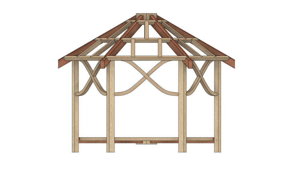
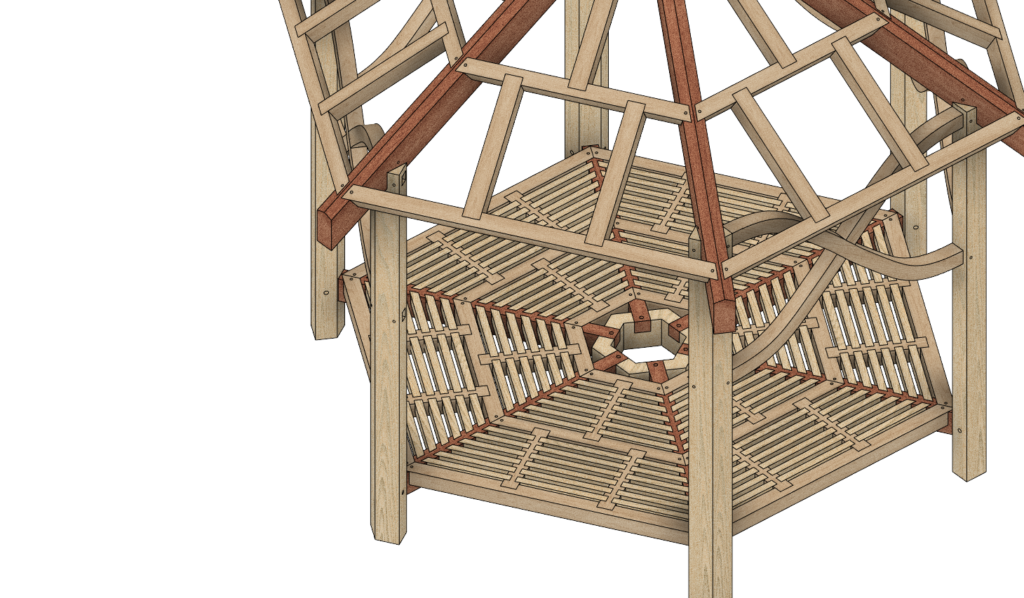
At this point, it’s a design in progress only. I’m not finished the design (missing seating, at least) and I’m not committed to building it, either. It’s a ton of work, though it sure would be pretty. I don’t know how to finish the roof without using metal fasteners (nails), so I think I may well go conventional there. So it’s not a pure timber-framed structure in that sense, but there’s a lot of TF joinery, for sure, which ought to count for something 🙂
And lastly, I leave you with this:
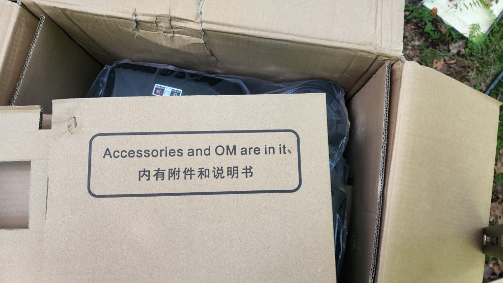
Evidently, the sawmill’s engine accessories meditate…