By now you must know that my existing power system in the W.O.G. doesn’t have the oomf to run my table saw and dust collector, which makes me sad. I bought a heavier AC inverter which certainly appears to be up to the task (and I sure hope so, as the investment in it, freight, and ancillary parts is about $4,000!), which arrived a couple of weeks ago. It has been slow going getting it installed, for various reasons, not the least of which is how much effort actually goes in to something like that. How much? You already knew I was going to tell you all about it 🙂
The new inverter cannot simply take the place of the old one, for various reasons. That’s okay because I can leave the old one in place to do what it is able to do (which also includes the solar charging system and generator charging system) and simply add this second inverter to the battery bus and let it power the heavy machinery separately. Of course this also means I need a second load center (that’s what electricians call what you probably call a “breaker box”), which of course means it has to go somewhere, have wire run to it, etc. So that’s where our tour begins.
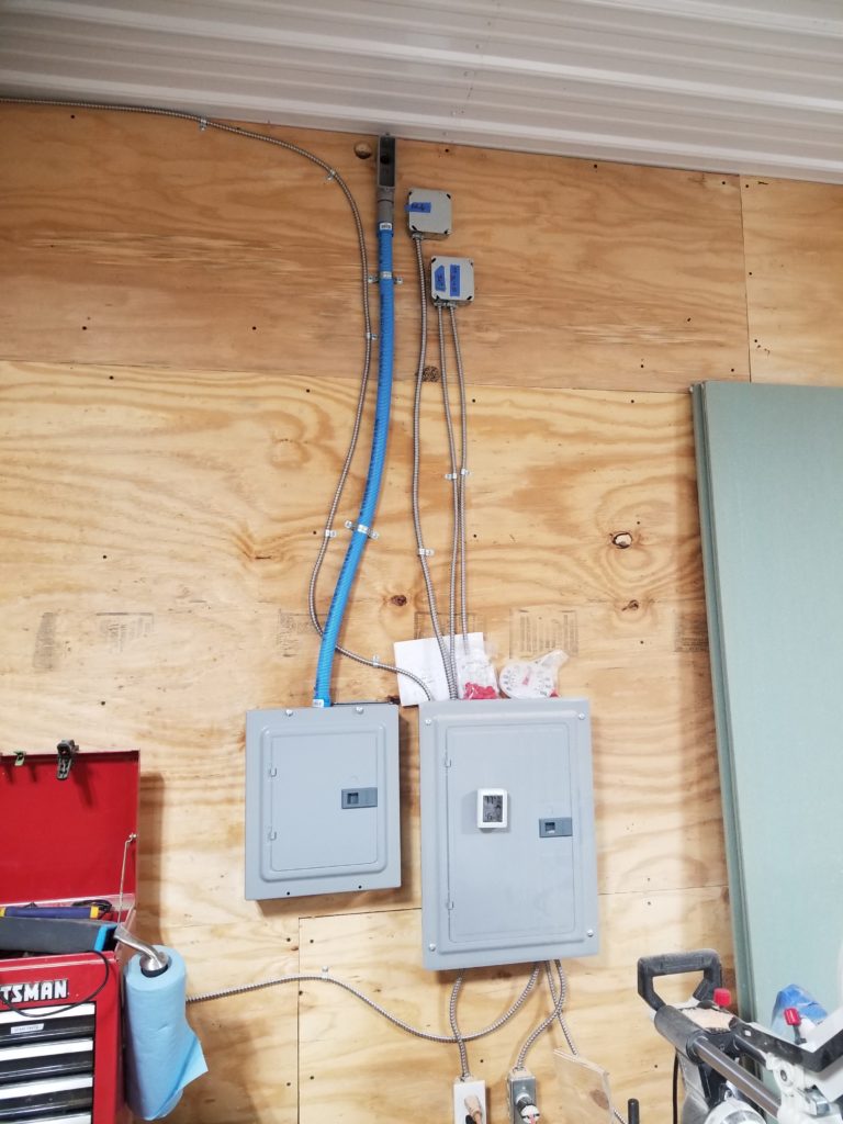
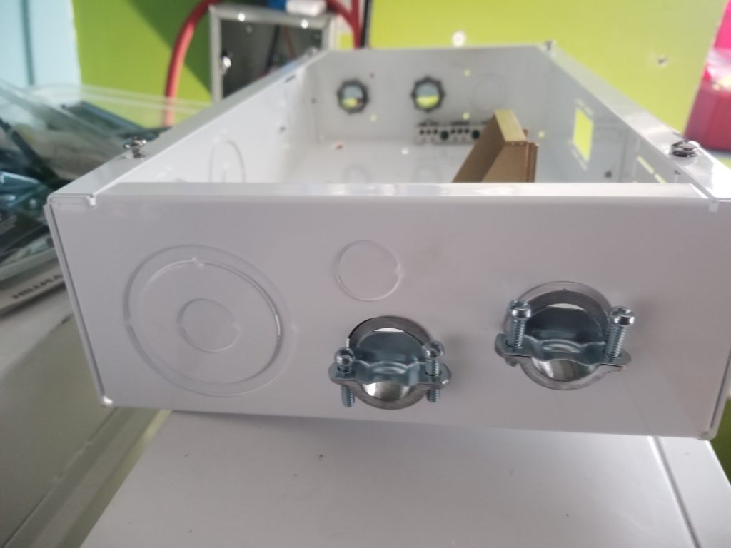
On the right, the existing load center that’s connected to the weaker AC inverter. On the left, the new one, which only has 8 positions (4 if you’re thinking 240V circuits, which these will all be), and that’s just fine. One each for table saw, dust collector, future lathe, and one to grow on. The astute observer may notice a hole adjacent to where the blue conduit body penetrates the plywood. Yeah, that was my bad. It’s really hard to drill through a finished wall and have things come out well because the depth (about 4.5 inches) magnifies any misalignment. The first hole was just an inch too high and intersected with the top framing member of the wall (you can see it covering half the hole from behind). Oops. I’ll patch that later. For now, I want to move this project along so I just drilled a second hole and got on with it.
Of course, on the office side of this wall, I never intended to have TWO power supply penetrations so it’s kinda cramped up there.
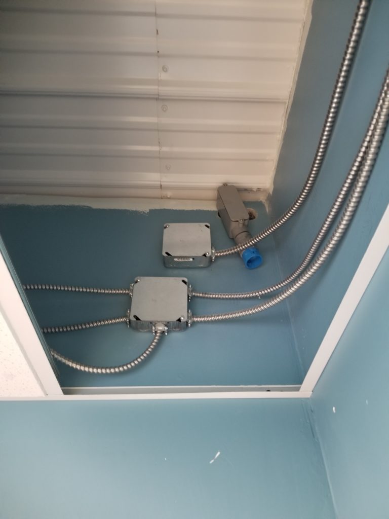
The gray conduit body with the blue adaptor will have some more of that blue flex conduit like that which goes to the load center. Why conduit? Well, I need to use AWG 6 wire here to carry the heavy current and you can’t get that nice armored cable in AWG 6. The conduit will keep it safe from mices and make it relatively easy to run the wires. I did not install the conduit because I don’t know how long it needs to be yet and didn’t want it flopping around from the ceiling without someplace to go, anyway. I will install the device that will accept the conduit (that’s the new inverter) first. Those white spots on the wall are deep scratches in the paint. And that’s why you paint AFTER you run your utilities. But not when your utilities run outside the walls, so there’s a danger of damaging the paint job. The whole room needs some touch-ups anyway, so I’m not gonna sweat it for now. When the weather gets warmer, I will touch up the paint as well as get back to the wallboard job for the mud room and the Executive Washroom. Both of those jobs want warm temps for the chemistry of the paint/joint compound to perform well. No sense spending a lot of energy to heat the space when I could just wait for the sun to do it for me in another month.
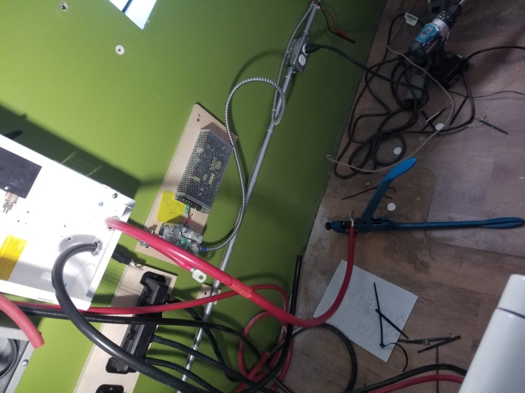
Now, back in the office, it’s time to figure out how to add a second inverter into the power corner, as well as a super duty battery breaker for it. That breaker is so big it needs its own box. This is how the power corner looked when I started (after rolling the battery dolly out of the way).
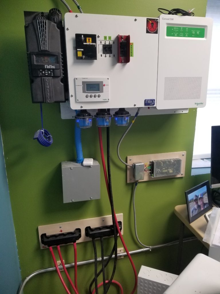
You’ll notice there’s really not a ton of room here. That’s true! I will mount the inverter on the blue wall to the left but there’s still more work to do and none of it is as easy as it should have been.
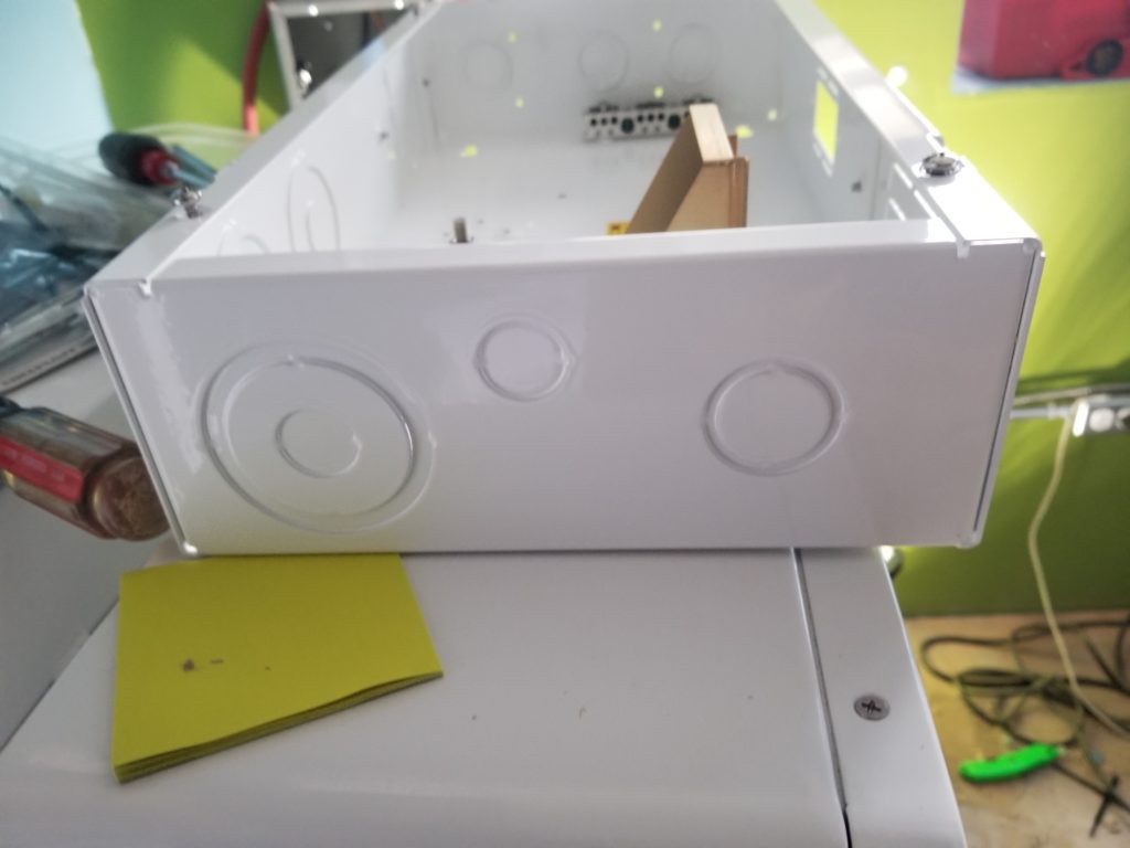
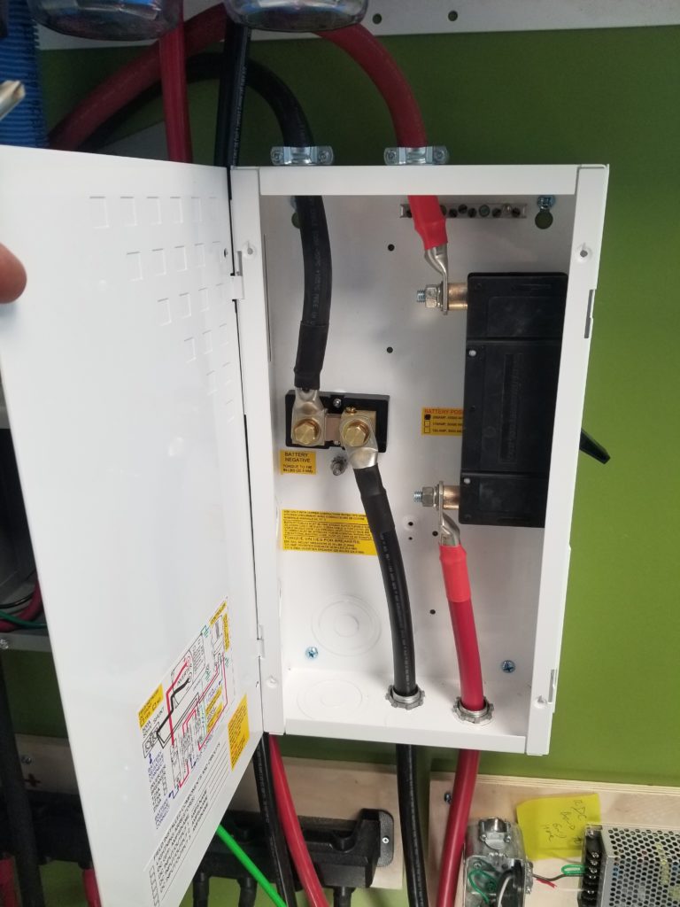
The first thing I need to do is prepare the box for the battery breaker so it can accept my Even More Beefy wires (these are 4/0 gauge, for those following along at home). Since these wires are exposed (and need to be, for ease of service and moving things around), I want to use ordinary cable clamps for them. The 3/4″ trade size worked well for the other battery wires, so I choose to use those here, as well.
For reasons unknown, while the top of the breaker box has three nice 3/4″ or 1″ (depending on how you knock out the plugs) — visible in the background on the left — the bottom of that box has a single 3/4 or 1″ port (right), a 1/2″ port (middle), and a 1/2 or 1.5 or 2.0 inch conduit port. Why not three at the bottom like at the top? No idea. This, however, is a temporary problem for me, since I want to run 2 wires in through 3/4″ clamps and then 2 wires out the top, ditto. The top is already good to go. The bottom, not so much. Enter the special hole saw specifically designed to cut holes for cable clamps in electrical boxes. I have one for 1/2″ clamps. Now I have one for 3/4″ clamps, too. A minute with the drill and presto, all four of my 3/4″ clamps are installed. Excellent.
Now all I need is a place to put it that’s close to the battery bus bars that also allows me access to the breaker’s toggle, as well. That toggle is on the right of the box, so the box needs clearance to the right. The only sane place to put it is where the 12V DC power supply lives now. What’s that? Look back at the first picture and find the square gray junction box. The power supply is to the right of that, on the plywood. It’s a little junction box and a silver mesh brick.
True to the maxim that before anything may be done, something else must first be done, in this case I need to move that 12V DC supply before I can mount the new battery breaker for the new inverter. Because of space constraints, it can’t live on the blue wall (left) and it has to be very close to the bus bars (under black covers, below square junction box). Okay, then, power supply moved.

Sadly, this also means there are wall anchors now exposed. Some of them will get covered by the new battery breaker but the others will need to be removed and the holes patched when touch-up time comes.
But now, now it’s time to mount the battery breaker in this nice new space I just made for it.
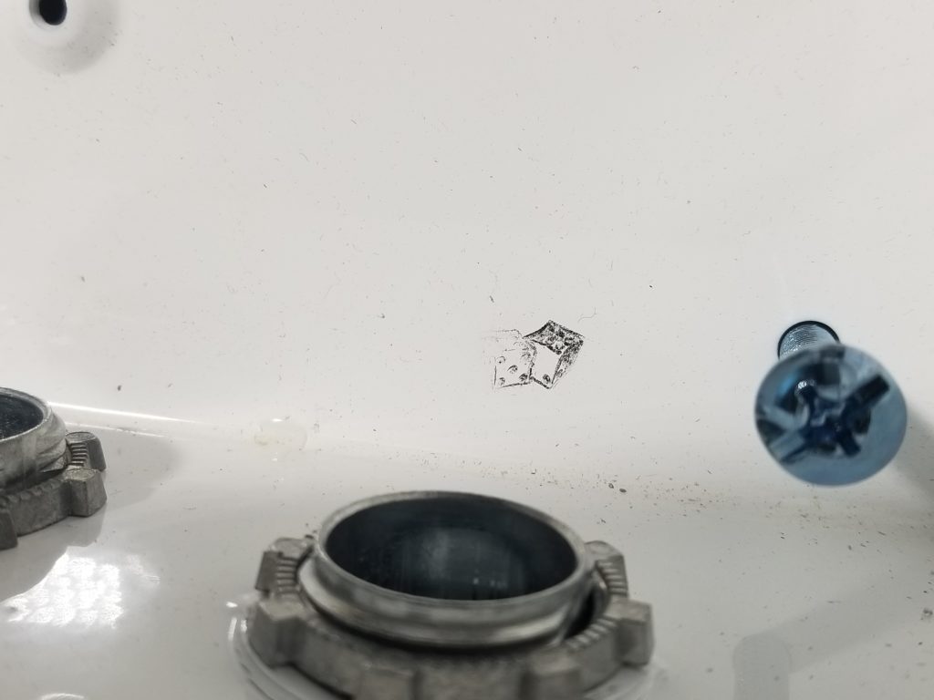
As I do, I notice this odd little stamp of a pair of dice on the inside of the chassis. The power center had a clown, if you recall. I suspect this is a thing with this manufacturer. I wonder if that’s effectively an inspector’s stamp or just someone on the line being silly.
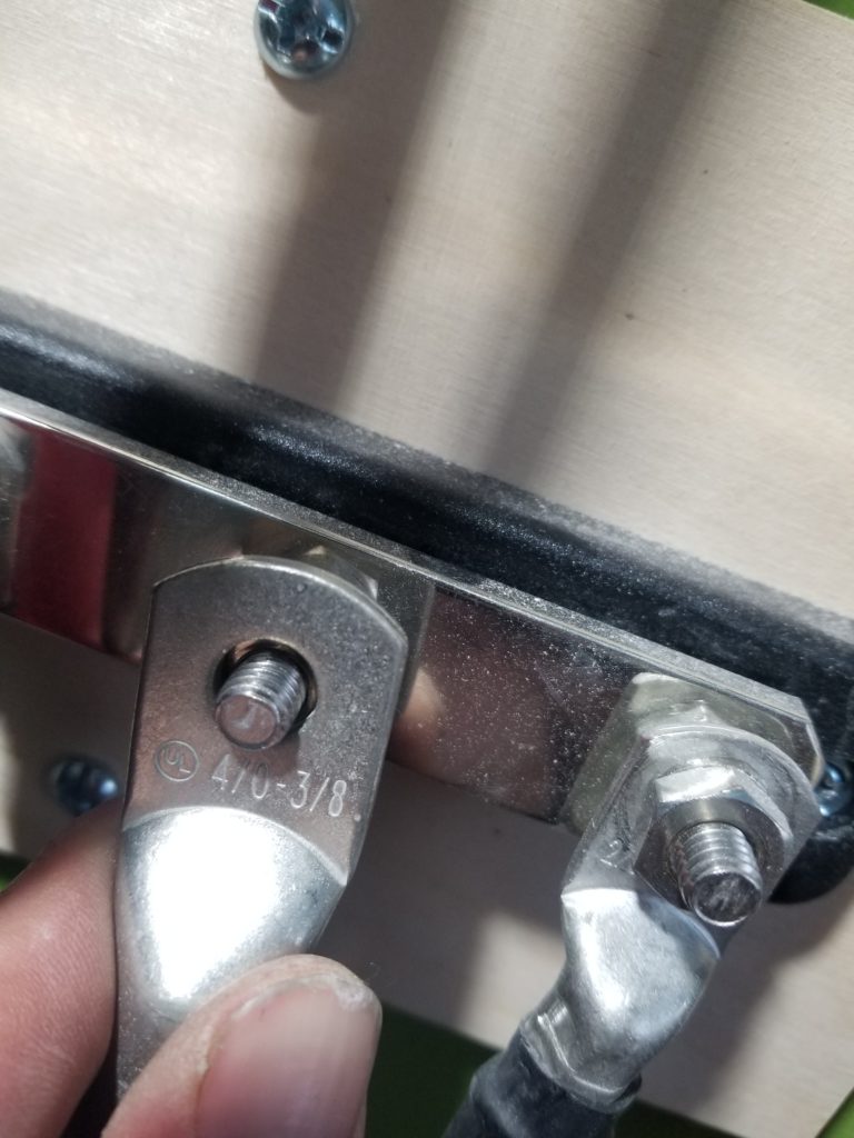
Time to feed the heavy 4/0 wires through my hard-earned 3/4″ clamp ports.
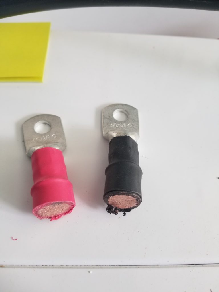
But no. I seem to have overlooked something critical. The lug connectors on the 4/0 cables are actually too big to fit through 3/4″ clamp ports!
The wires fit through snugly, but the lug connectors are too wide. Shit. I don’t have 1″ clamps, I don’t have a 1″ hole saw anyway, and I really don’t want to put this off and have to re-work everything I’ve done already. It’s a big pain to make a 3/4″ hole into a 1″ hole anyhow because there’s nothing for the hole saw to use as a guide. There are ways, but it’s a bother. Hm. What to do? I know! I actually have a bag of lugs that came with the wire I was going to use to go from the battery breaker to the inverter proper. So if only this Very Thick Cable didn’t have lugs on it already, I could just thread it through the clamps and then attach the lugs. Sure, I can do that. I just have to figure out how to remove the lugs that are there. Ordinary wire cutters are no match for this stuff.
I actually wound up using a reciprocating saw and a metal cutting blade, which was a bit aggressive but got the job done without too much fuss.
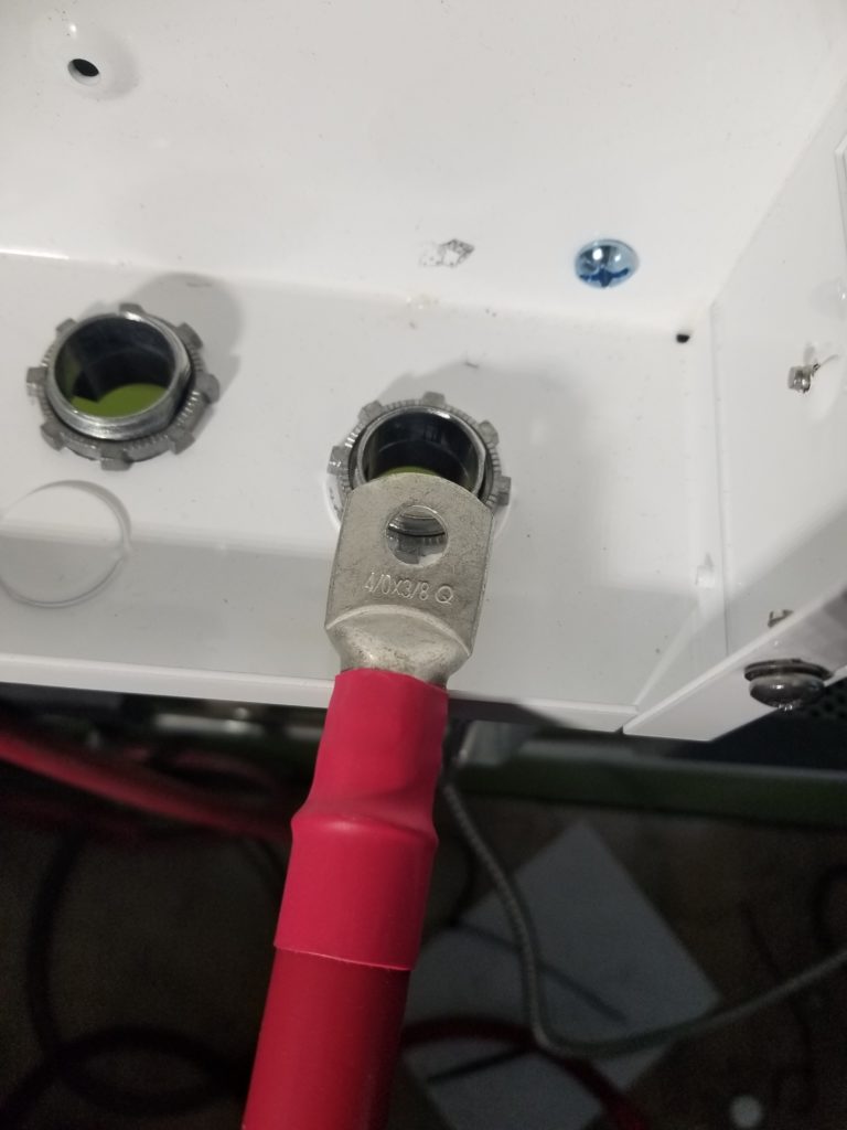
Now thread the naked ends through the clamp ports and bring those ends to my crimping tool to put new lugs on them, which will be captive (but I don’t care). It’s slightly ridiculous, but it gets the job done. Shown here, the red wire coming down to the floor to the crimp tool which needs to rest on a solid surface because of the force required to secure the lug to the wire.
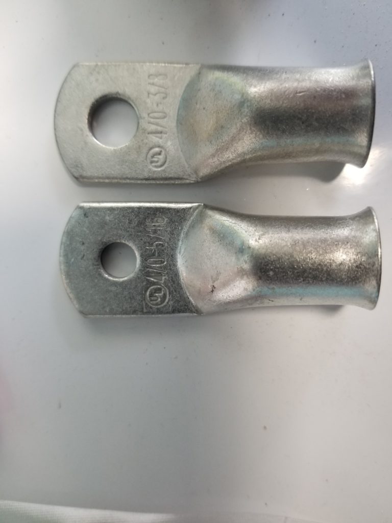
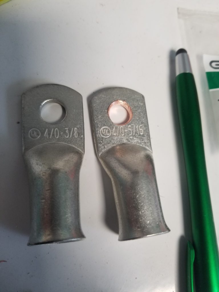
My little bag of lugs came with a pair of 5ft lengths of wire. I was surprised it came with TEN lugs, but whatever, maybe it’s a standard pouch of lugs and it’s easier for the vendor to just include that same pouch no matter how long the wire is. That makes some sense. What I failed to notice, though, was that of those ten lugs, there were actually two kinds! Five each with 5/16″ holes and 3/8″ holes. What difference does it make? Well, it matters. Most of the studs in this system are 3/8″ (6/16) so those 5/16″ holes simply won’t fit around them. Wouldn’t it have been nice to notice this before I installed the lugs on the wires? Yep, it would have been very nice.
Well, crap. Okay, then, cut off the one that’s too small, install one that’s the right size. And now, after much ado, the battery breaker box is installed and has all the big wires going in and out of it as necessary.
It turns out I have the opposite problem on the bus bars. Those are sized for the smaller lugs. The existing lugs on the cables are kinda sloppy when installed. No bueno. There needs to be a lot of contact. I cut off those lugs and used some of my surprise stash of 5/16″ lugs in their stead. Even so, now that the lug fits on the stud, it still doesn’t have great contact area. To mitigate this, I put the lug directly against the bus bar instead of sandwiched between nuts. The sandwich is fine for the smaller wires that don’t carry as much current, but for these, which will carry quite a lot (over 200A for short periods and easily 100A for many minutes at a time), a lot of contact area is critical.
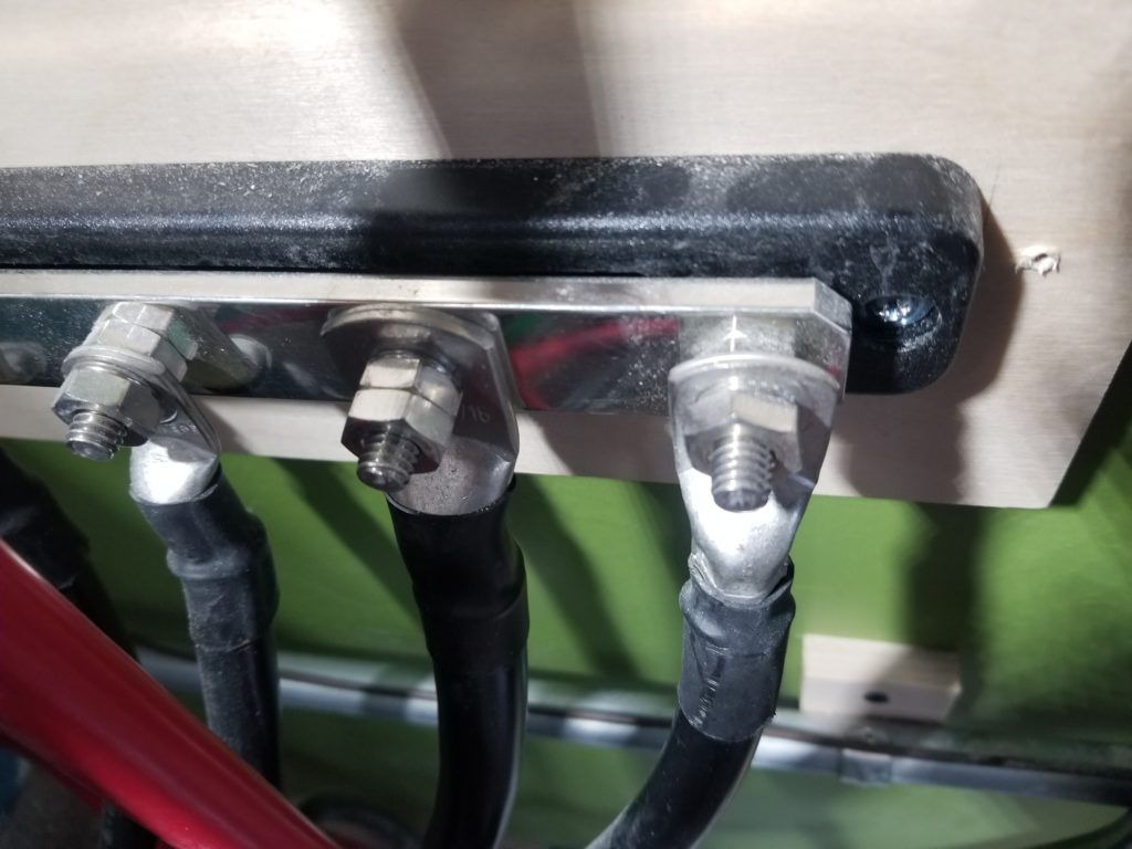
Actually, now that I’m looking at this, I don’t really see a good reason not to put ALL the lugs flat on the bus bar. It could only help. The bars arrived with two nuts and a lock washer between them, making it pretty obvious that the intent was to mount the lugs between the lock washer and the back nut, but thinking about it further, I’m not so sure. These systems have been running fine for months as-is, but I think they will be better to have the lugs flat against the bars, especially as warmer weather approaches and power consumption increases for both the residence and the W.O.G. It’s not a lot of work to change it, though both sets of bus bars are not exactly in convenient locations and I have to shut down the whole power system to work on them safely, so it’s not nothing, either. Best done in daylight and fair weather.
By the time it was all done, and because the number of lugs in the bag was an odd number of each size (why?!), I had one 3/8 and one 5/16 lug to go to the inverter, which wanted 3/8 all around. A short job for the drill and presto, my 5/16 lug is now a 3/8 lug.
And somehow this job wound up taking most of the day just to get it this far along. Well, it includes actually mounting the inverter (at well over 100#) to the wall, too, but that was relatively easy.
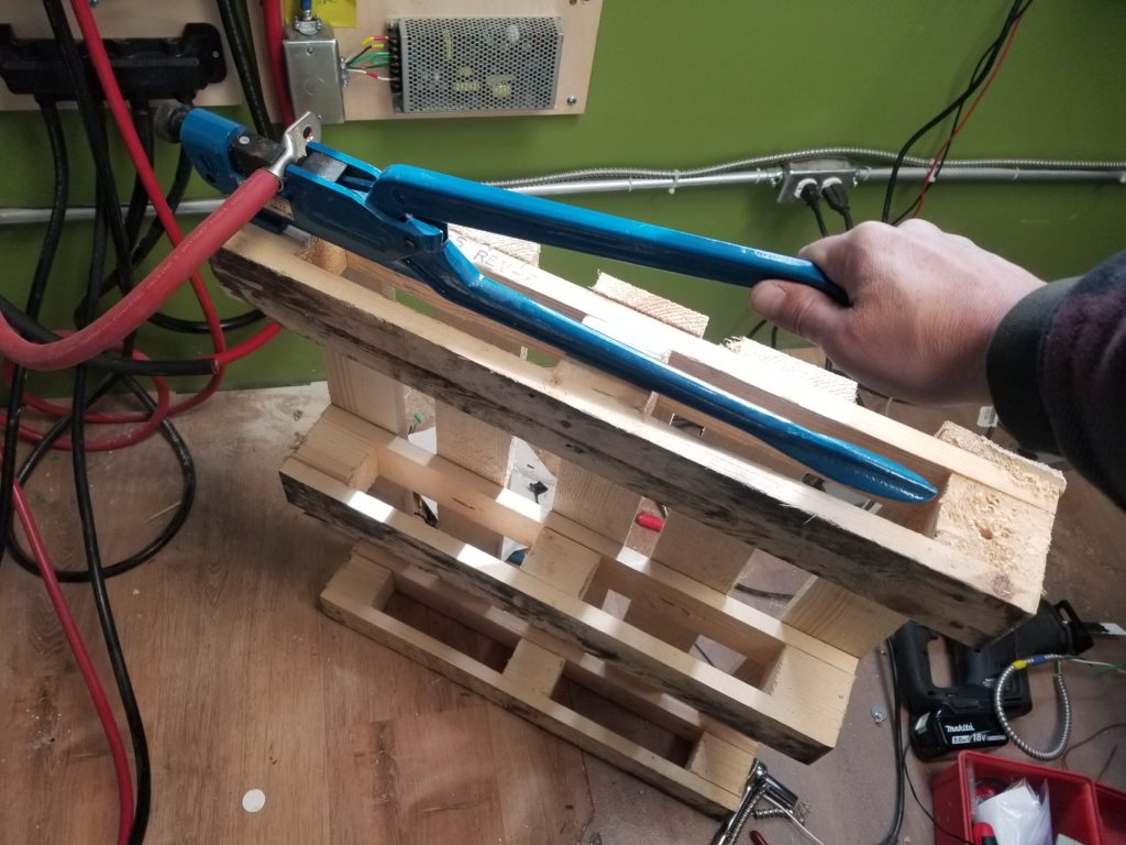
Crimping these lugs onto their wires was a little more fun, since they weren’t long enough to reach the floor where I had been bracing my crimp tool for all the others. A little improvisation was required. Hey, look, a second use for the mini pallet the inverter came on!
And now nearly done.
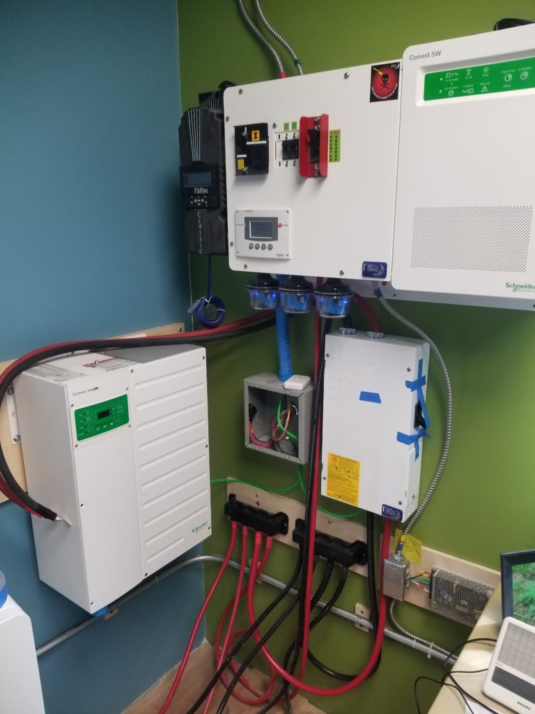
That’s the new inverter on the blue wall. I haven’t hooked up its battery wires yet – they are switched off for now. I will hook them up in a day or two when I return to this task (including re-positioning the lugs on the bus bar studs, while I’m in there). There is one more device to add – it’s small – that is used to both monitor and configure the inverter. And then there’s finishing the conduit (you can see the blue coupler in the lower left corner of the inverter) run and pulling all the wires through, too.
So, yeah, installing a second inverter is a bunch of work. In this case, more work than it strictly had to be due to differing lug and stud sizes, cramped quarters, and an oversight regarding cable clamp compatibility… and so it goes. And so it will continue for a few more work sessions before it’s ready to power up and discover if it actually solves the problem it was meant to solve (powering the larger machines). I sure hope so…