It sure seems like it’s taking a long time to get the power system operational. And it is, but only because before anything may be done, something else must first be done, and it turns out that recursive dependency goes on for quite a while. I’m close, though! Really.
For routine wiring operations, I don’t usually bother to make a plan. It’s usually quite simple – a cable or two from point A to point B, connect the ends to the things they connect to, done. In the case of the office, though, some of the wiring gets positively interesting, as there are multiple circuits, pass-throughs, three-way lighting, and some creative distribution employed to minimize wire runs and maximize the use of effort spent running them. So yeah, in this case, I do have a plan and it looks like this:
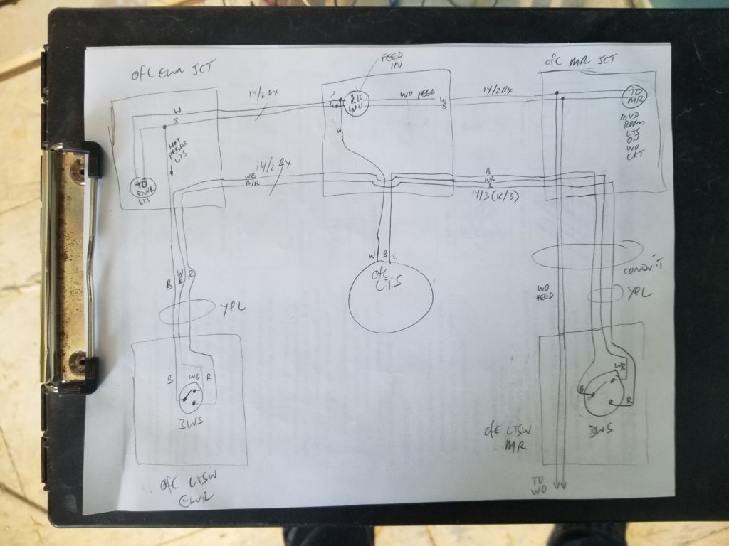
You can see why I needed it! Each of those big squares is a junction box. There are multiple functions and multiple circuits and transitions from armored cables (“AC” as the manufacturers call it, “BX” as a lot of electricians call it – the same people who call the plastic-jacketed stuff “romex” instead of “nonmetallic cable”) to metal conduit. There are three-way-switches and power feeds to other rooms. None of it is “complicated” per se, but there’s enough going on here that being able to look at a junction box with five ports in use and know what’s coming and going from each of them is worthwhile. It’s just a little too much to simply keep in mind and anyway, it’s always better to have a drawing so each stage can be inspected and verified. This greatly enhances the chances of having it be right the first time 🙂
In case you were curious “Yel” simply means “these wires have yellow tape on them”, a technique I use to identify different circuits when more than one circuit is present in a junction box. I even have a color coding scheme for that – yellow is usually for lights (also used for power from solar panels), blue is for water (such as well pump), green is for generator (“greenerator”!) or more generically for primary supply feeds. White, red, and black are reserved for their more customary meanings (white = this wire is neutral, no matter what color the jacket is; red = this wire participates in switching and will at some point be connected to hot; black = this wire is or will be connected to hot, no matter what color the jacket is). The tape markers more than anything identify wires that are doing anything other than what their natural jacket color code would indicate. Why use wires with “the wrong” jacket color? One doesn’t always get to choose. When using BX or romex cables, there’s a white, a black, and sometimes a red in the bundle. That’s it. If you don’t have traditional white (neutral), black (always on hot), and red (switched hot or second hot for split 240V feeds) roles for those wires, but you need three wires, you tag them with tape to indicate their newly assigned roles. And you draw a picture. When the pictures get really interesting, I sometimes leave a copy of the drawing in an envelope tucked behind the junction box as a kindness to future-me. Who knows how long it will before I care about the wiring again – probably much longer in the future than my memory of what I did will last.
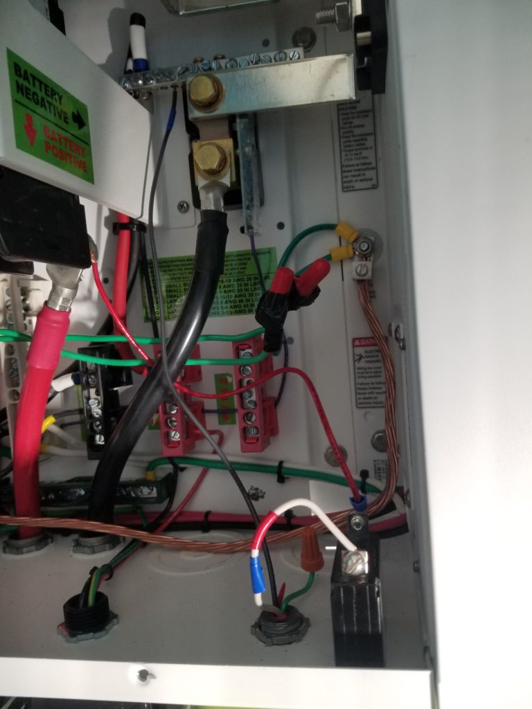
Anyway, back to the actual wiring! Among other things, I need to hook the generator line, the solar line, and the AC inverter output cables all to the power center I have just mounted to the wall. I also need to install a tap directly off the battery to go to the 12V DC power supply for the propane furnace. The battery cables themselves are these massive 2/0 cords – bigger than most automotive battery cables or arc welder cables – and there’s no easy way to tap those for a thin wire to go to the 12V supply. In the house, this was easier because there were multiple batteries and those all came together at a bus bar and the bus bar had both massive lugs to receive the massive cables and some small taps for just this kind of thing. I don’t have bus bars in the office system. I will, actually, but those bus bars don’t have small taps (don’t ask me why). Okay, then – how about something better – tap the battery feed inside the power center. That gives me a nice place to put my low power DC breaker for that line, too. In the house, I mounted that breaker on a separate bracket by the external 12V DC power supply, but it would be even better to have it in the power center, where all the other DC breakers are. Of course there’s no place to mount it.
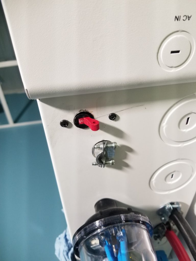
And by no place, I mean of all the mounting places that do exist, none of them would accommodate this exact thing. No problem! The great part about having tools is one can do stuff with them. That includes creating mounting points where none existed.
Some of my precision drilling equipment is still in a box somewhere, so this job was a little more sloppy than it might have been, but the job got done. That little black rectangle in the lower-right corner of the inside view is the DC breaker and the white wire with the blue and red tape (and the black wire that’s hard to see behind it) are the breaker-protected DC feed for the as-yet-to-be-installed 12V DC power supply.
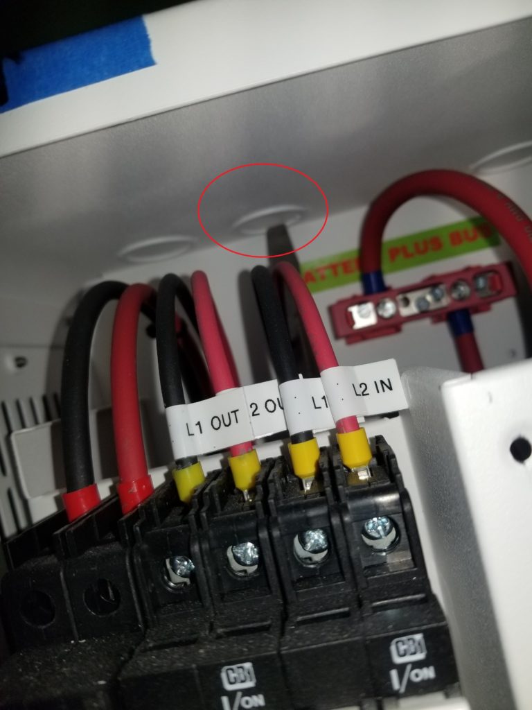
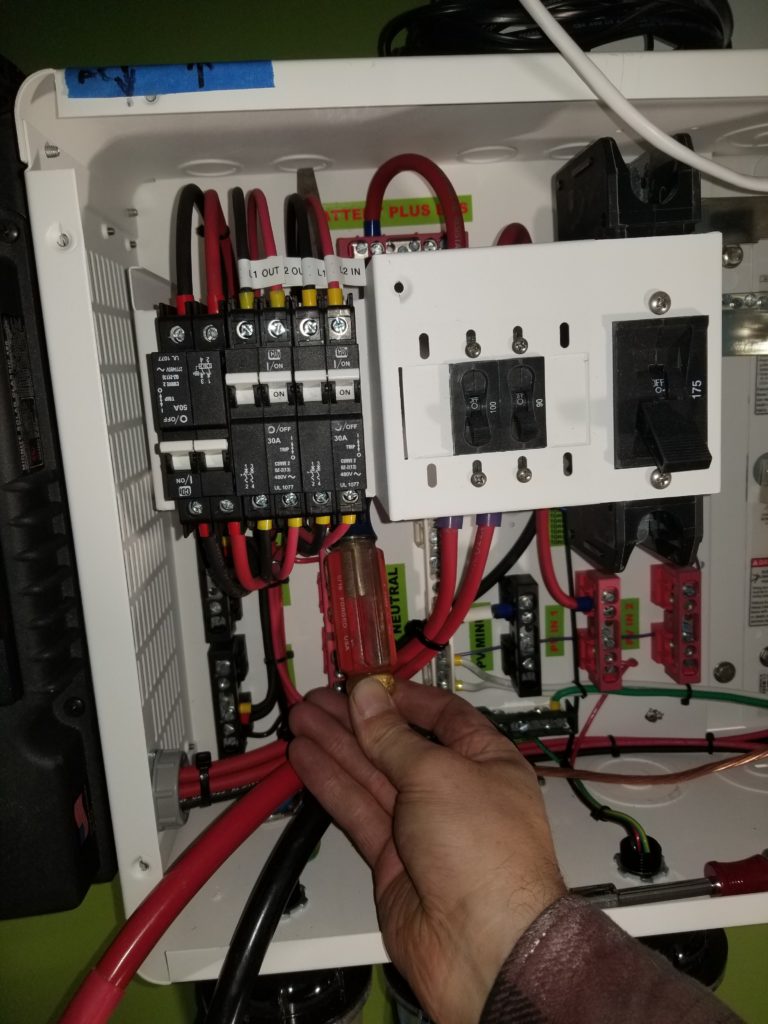
Inside the power center, it seems like there’s lots of room, but somehow it’s still quite crowded in there. Take for example this knock-out (red circle, photo at left). In order to knock out that knock-out and install a cable through the hole, I have to somehow get behind the bank of breakers and hammer upwards to pop it out. But upwards from where? The box is full of other stuff!
Answer, use a screwdriver carefully routed behind all the delicate parts and use some heavy lineman’s pliers as a hammer to gently tap the handle of the screwdriver (where my hand is in the photo at right) to dislodge the knock-out at the tip. Sure, it can be done, but it could certainly have been easier.
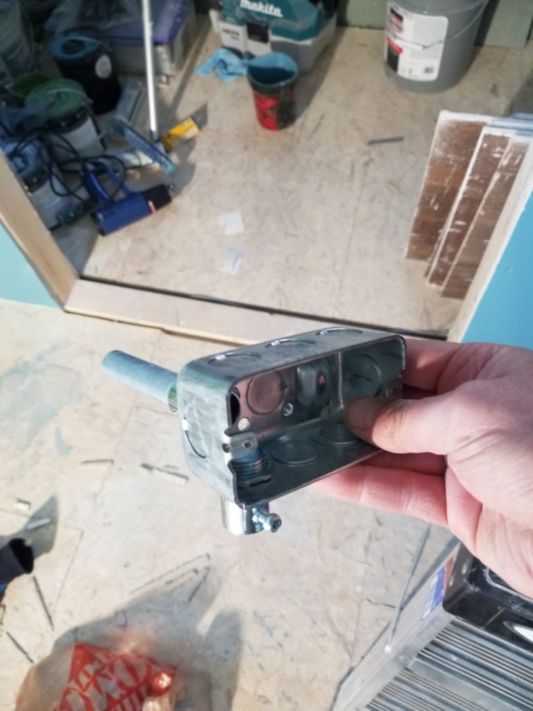
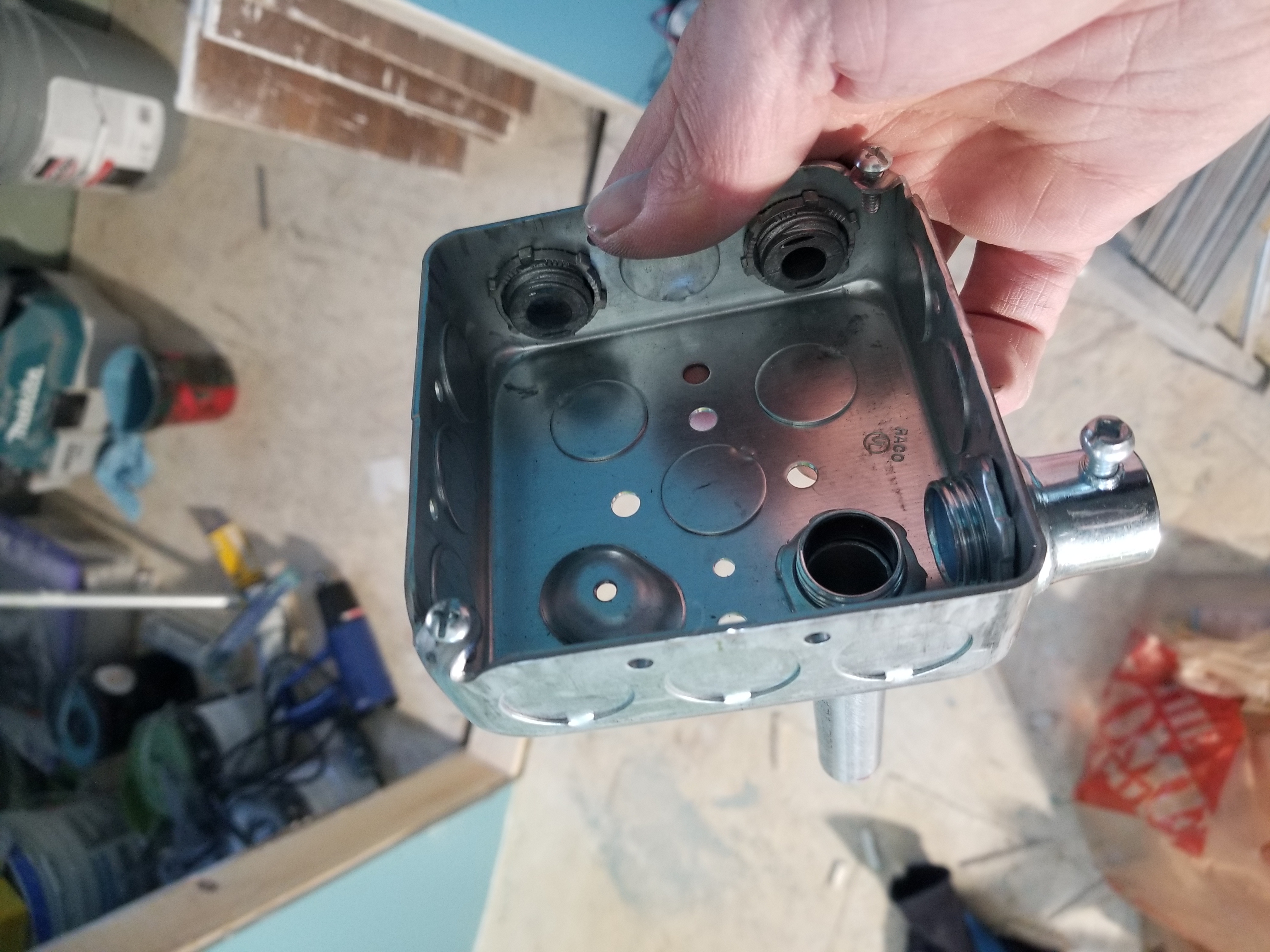
An amusing aside – what’s wrong with this picture?
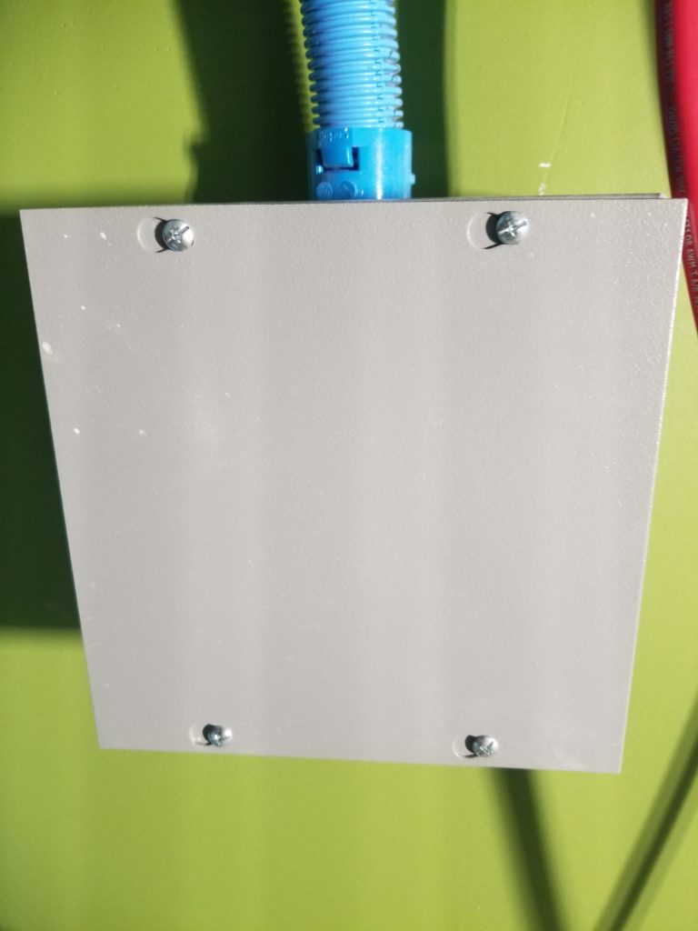
This is the junction box where the heavy wire from the long haul to the solar array comes in to the office and transitions back to the relatively thin wire (#10 AWG) that will connect to the power center. The thin wire is all that’s needed to handle the actual current, but given the long distance (over 100 ft), I opted for beefy cable to cover the distance so there would be minimal line losses. It was an expensive and inconvenient choice, but an important one where the winter daylight shines for only a few hours and not brightly enough to provide power every day.
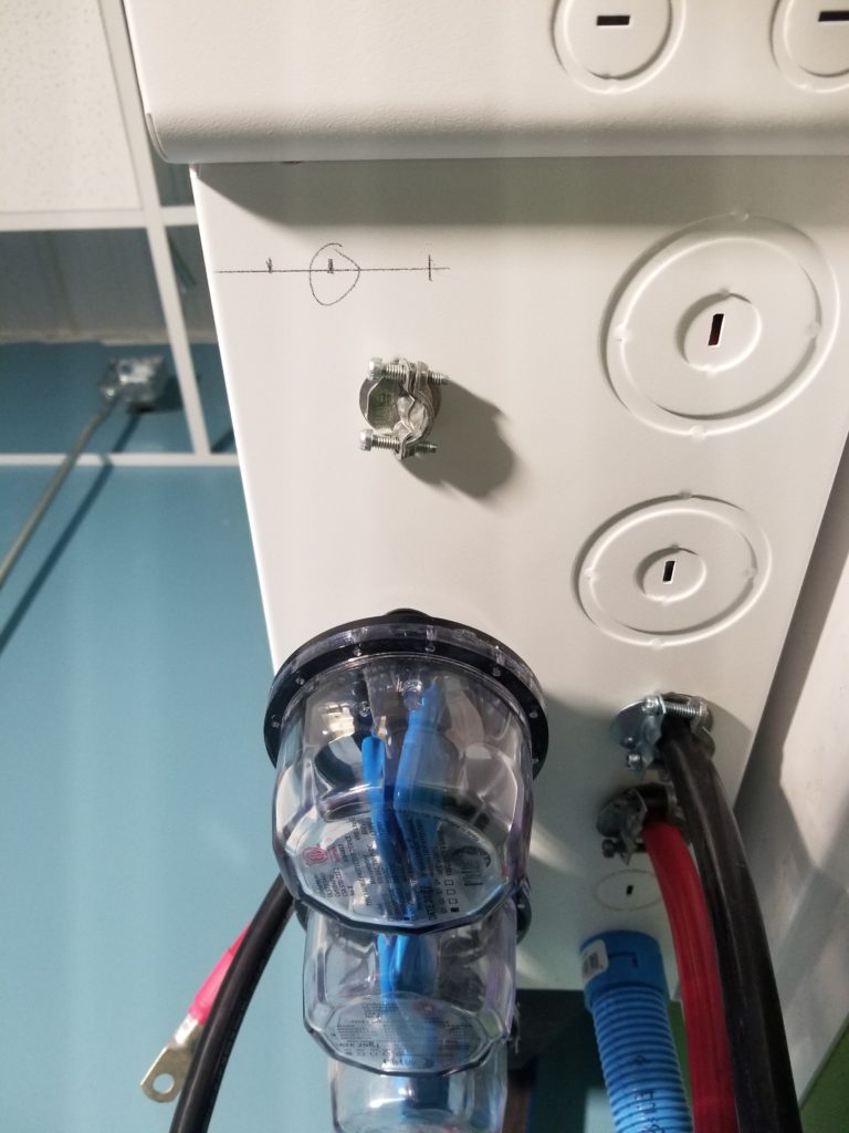
But what’s wrong with the picture? It looks okay, right? Just a gray metal box and some plastic flex conduit going up to the power center. Simple enough. The especially astute observer will notice that the keyhole slots on the cover are horizontally oriented. They’re supposed to be vertical, with the narrow part of the hole resting on the screw shank above it, not to the side. This lets the cover hang nicely on the screws before they are tightened. As installed, the cover wants to slip to the right before the screws are tightened. Oops. Way too much trouble to fix it now and it doesn’t really matter much – I’ll probably never open this cover again – but it is a little funny. In my defense, the box itself is perfectly square and symmetric except for the screws – there’s no hint inside which way is up. I just wasn’t thinking of the cover when I mounted it to the wall and that was that.
What remains to do? Well, I need to hook up the battery module to the cords coming from the power center and I need to finish installing the circuits that connect the breaker box to the lights, switches, and outlets. And I need to install the 12V DC power supply so I can energize the propane heater to keep the battery module from freezing. Much of this is in-process, but clearly there is still work to do!
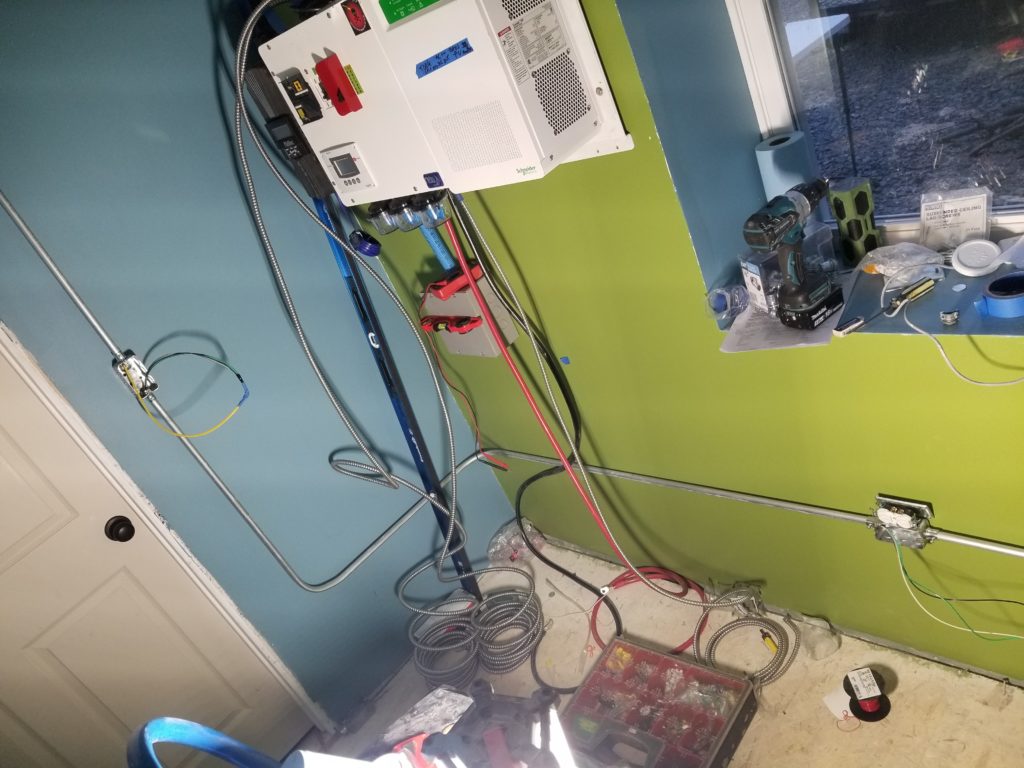
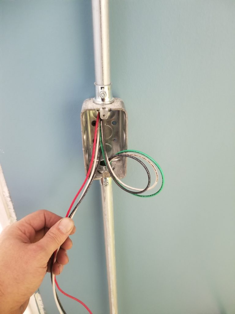
The wires on the right (green, white, black) were pulled from the outlet. The wires on the left (black, white, red) are for the switch only and start here. They have yellow tape markers on them so I can tell which set is which up in the ceiling junction box.
Sometimes, it turns out that a junction box just gets too full and needs to be bigger than I thought it would. It is a bother to undo and swap in a bigger one for a smaller one, but sometimes ya just gotta.
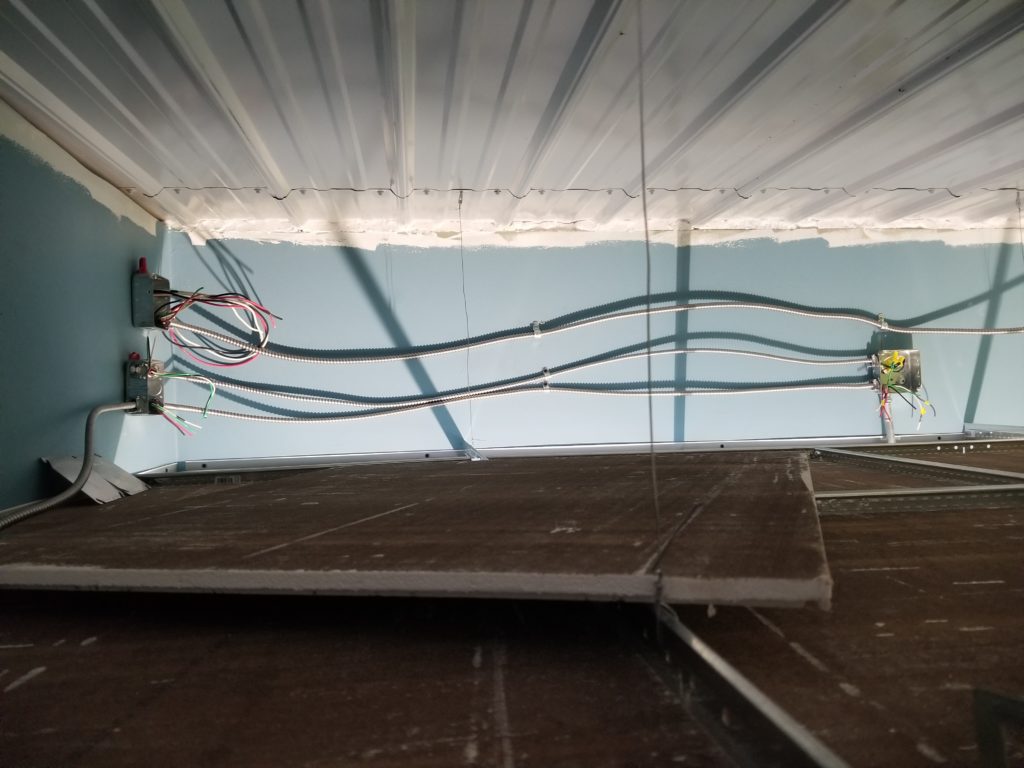
For your viewing pleasure, a snapshot of some of the above-the-ceiling work in progress.
Will the power system come alive today? I sure want it to, but I’m also kinda tired of constant work and could use a day off… but I could also be very happy to be able to start using my office for next week.
What did I choose? I spent the day finishing the electrical work (there’s actually one simple pass-through that happens to be behind my chop saw that needs to be hooked up, but the rest is done). I was just about to hook up the battery module when I realized two important things:
Thing 1. I’m tired and my brain is spent. This is NOT the right time to be configuring the charging system and the inverter for the battery.
Thing 2. I’m going to buy a second battery which means there will be bus bars and some other interconnect going on — it probably make more sense to just wait until it’s here and then install & configure the whole thing as-is. Otherwise, I’ll just have to configure things twice and re-wire the batteries when the other one comes. I’m not sure it’s worth it, especially since the next few days are forecast to be VERY cold.
So I spent the rest of the time installing the finish floor instead.
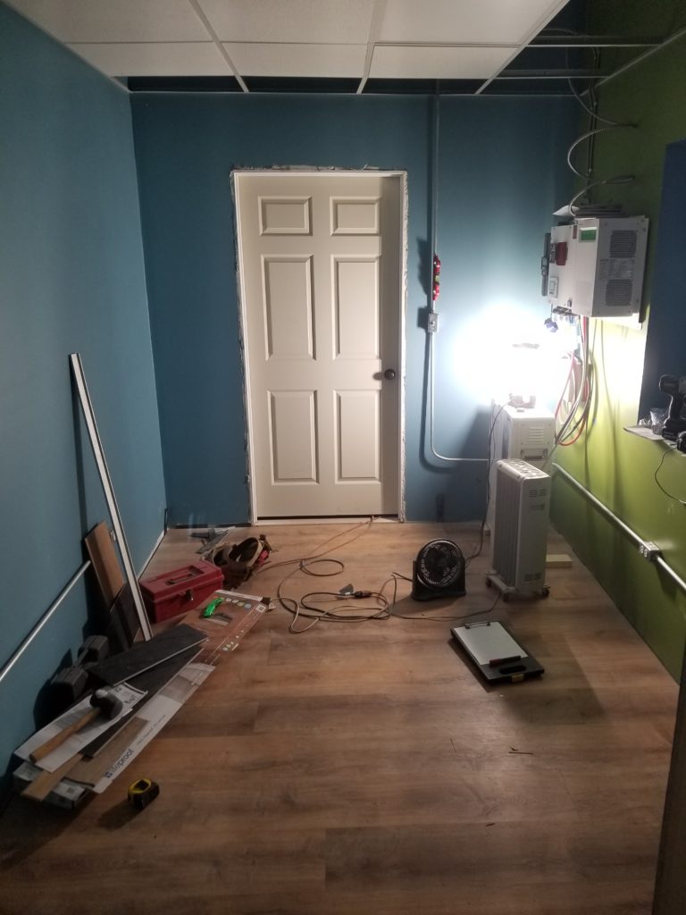
This is an interlocking vinyl plank system with integrated underlayment. It seems easy to install but in practice it was pretty finicky with the interlocking features. I used my rubber mallet a lot and even so wasn’t delighted with the process. It looks nice, though, and is theoretically water proof and abrasion resistant, as well as pretty nice looking.
And remember that 5-port junction box with all the action? This is what it looks like all wired up.
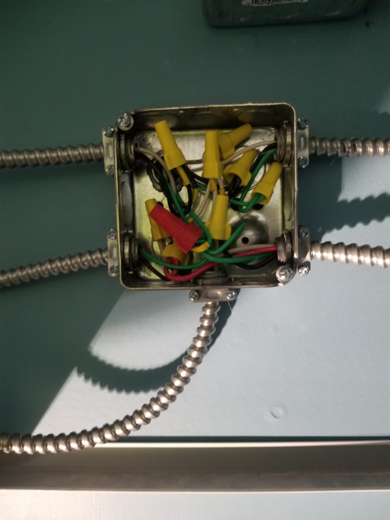
And THAT is why I really needed a drawing.
It’s actually technically a SIX port box – five cables connect on the sides and one length of conduit goes into the wall to meet a junction box on the other side.
So why the BX cable and conduit rather than just plain romex? MICE. That’s why. Mices like to chew on romex. Chewed romex is a fire hazard among other things. No, thanks. I know for sure there are mices already visiting the W.O.G., so I have every reason to believe they’re going to stay. Things may change a little when I have a proper garage door on the other opening — my quickly built barn doors leave plenty of room for mices to come and go — but I doubt it. Maybe when the power system is operational and the front door doesn’t stay cracked open to pass the generator cables, they’ll stop visiting — but I doubt that, too. Mices manage to get through some pretty small holes. The armored cable and conduit is definitely more work and more expensive, but it is 100% mouse resistant (they won’t eat aluminum or steel) and that’s what I want.
