Ah, the furnace. You know, the one I tried so hard to get both the unit and the thick-wall kit in the same place at the same time, which as you may recall, took our intrepid builder to Sketch E Commerce, a handful of other vendors, at least one wrong-thing-sent, and, finally, at long last, the NT20-SEQ furnace and the necessary special order, hard-to-find, thick-wall intake pipe were all here. It took me a while to figure out the very best place to mount it, considering all the things (propane lines, return-air paths, hot air output and things that shouldn’t be in front of that, etc), and finally settled on above the fridge. It’s odd, sure, but otherwise dead space and as it turns out, this time I got lucky. The furnace, plus a sleeve to hold it yet allow it the necessary clearances, leaves me with 61 inches to the floor from the bottom of the sleeve, which is otherwise as high up as it can go, essentially pressed up against the gray water drain manifold. The fridge meant to go under it is… 60 inches tall. An inch of headroom. Amazing! Seriously, given that the decisions which drove this situation span 3 projects and about as many years, the fact that it all adds up okay by chance is indeed amazing. And yet it is so.
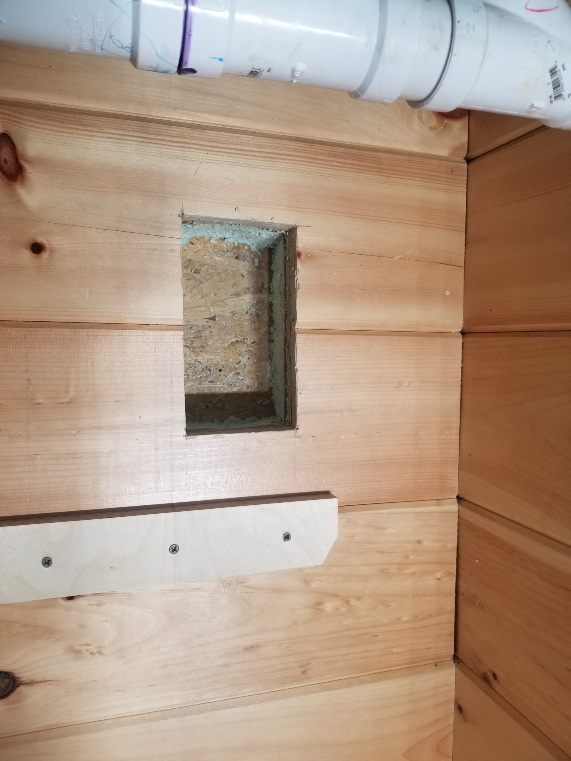
Since the furnace requires through-the-wall exhaust (as well as intake, for that matter), some very careful measurements are required to get those holes drilled such that they align perfectly with the ports on the back of the furnace. The duct pipes to the outside are to slide through these holes and telescope onto the corresponding members of the furnace and they must not touch anything along the way, so alignment is key. Well, I would imagine the fresh air intake for combustion doesn’t need to be stood off, but for sure the hot exhaust port does. So I measured it like 7 times, comparing the installation manual’s drawings with the actual unit because sometimes they lie. Then I put a cleat on the wall, added a shim the thickness of the floor of the mounting sleeve (which is essentially a close-fitting cabinet), thus creating a reference for the seating plane of the furnace itself, to which all measurements are relative. Then, with great care, I measured out for the holes. Measured again. Measured again. Checked against the unit itself. Checked against the manual. And then I was sure.
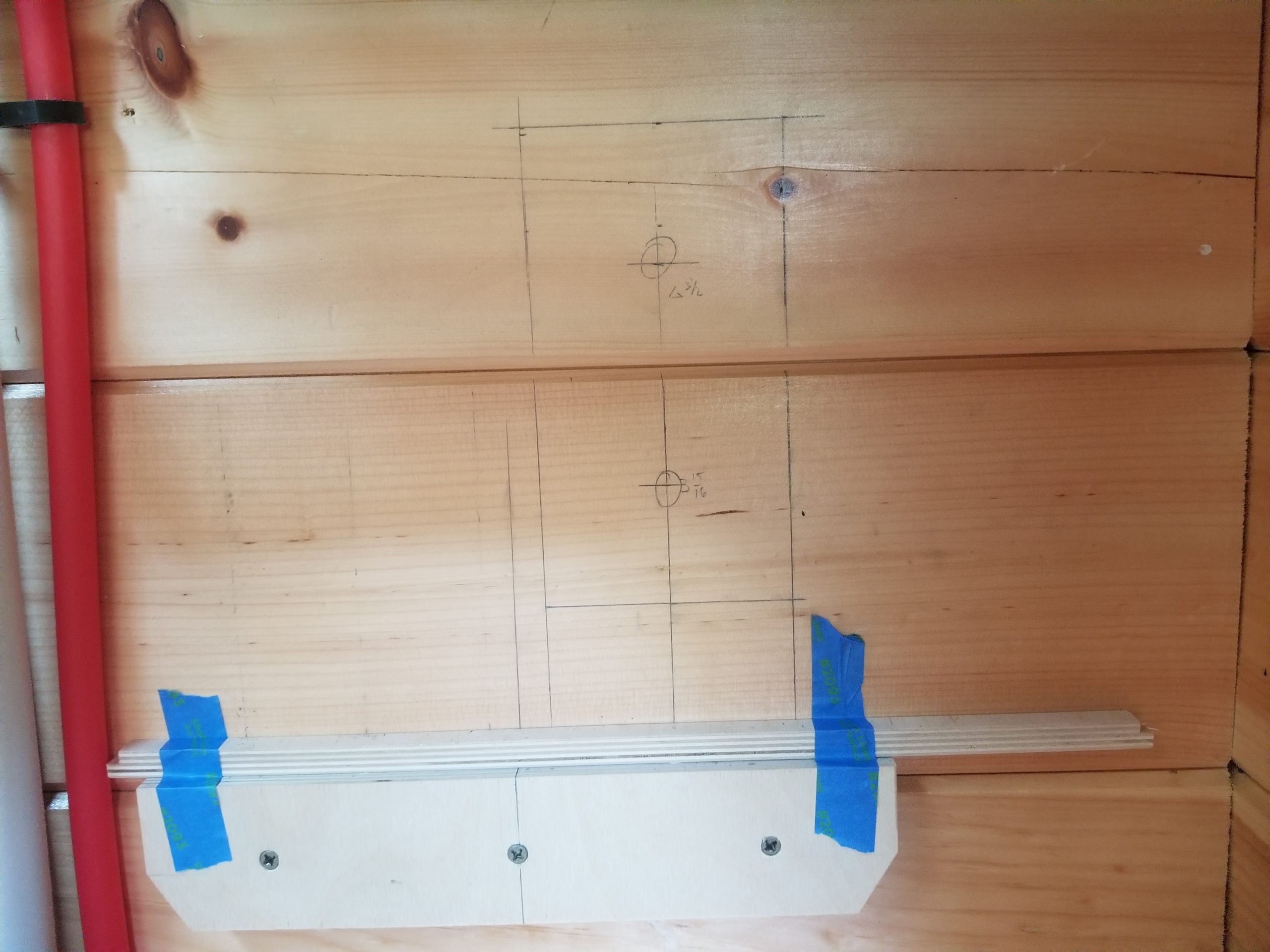
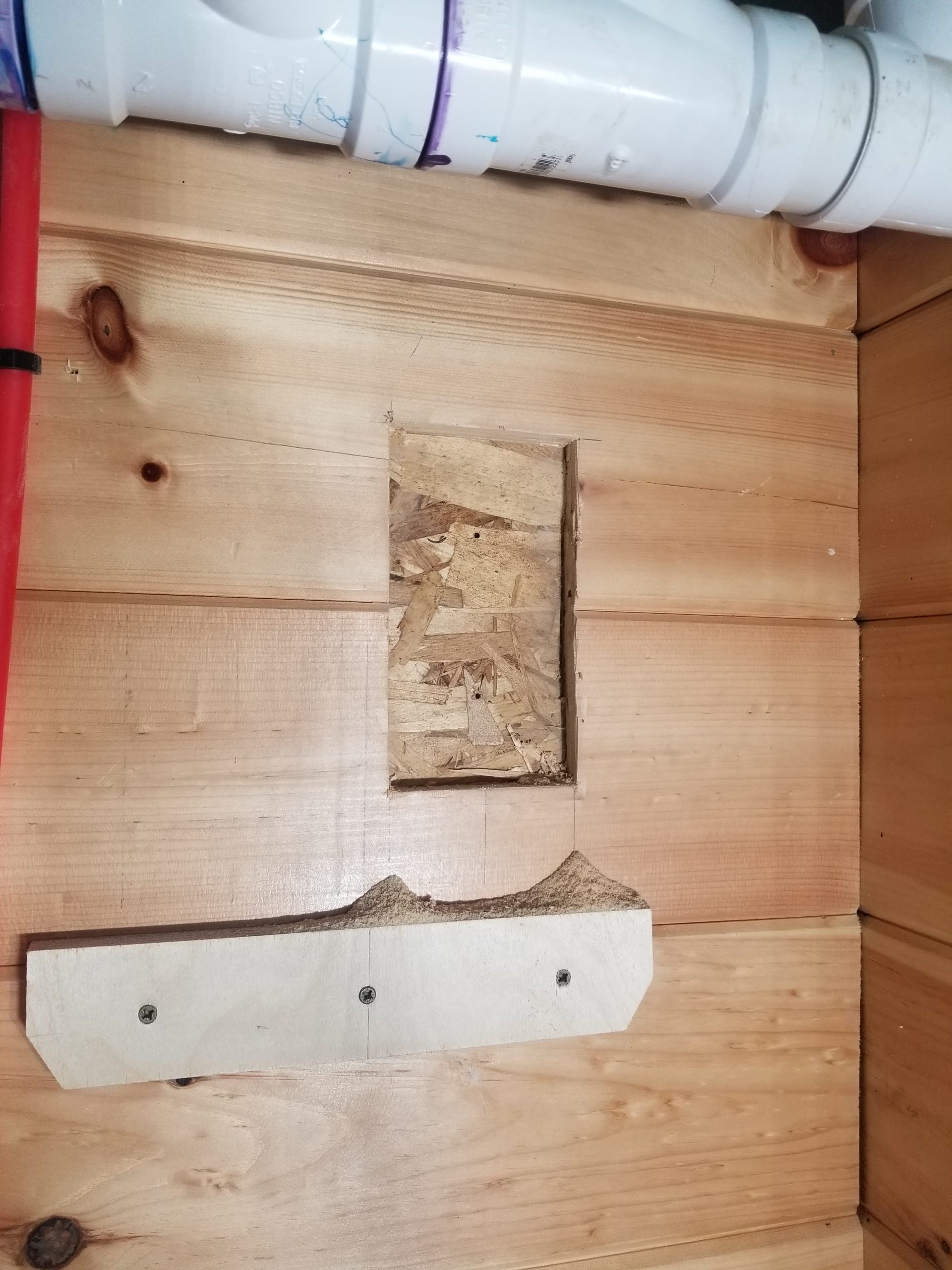
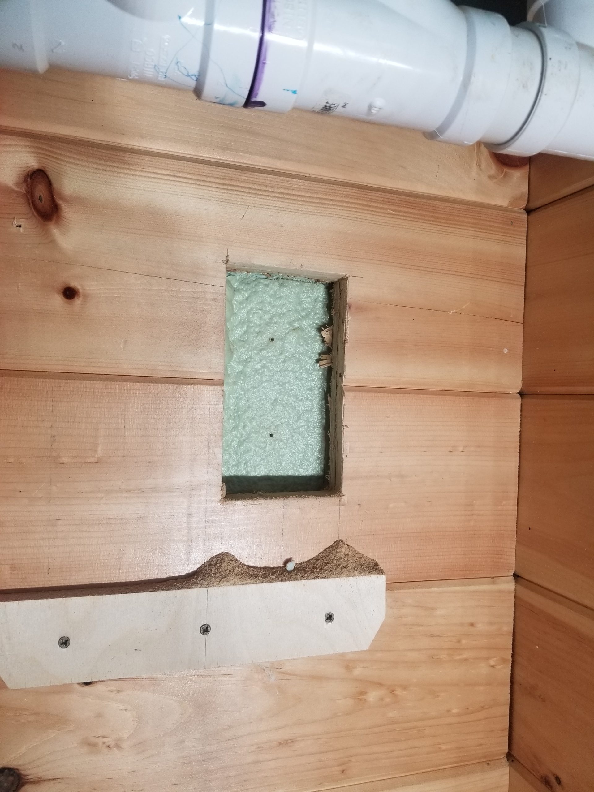
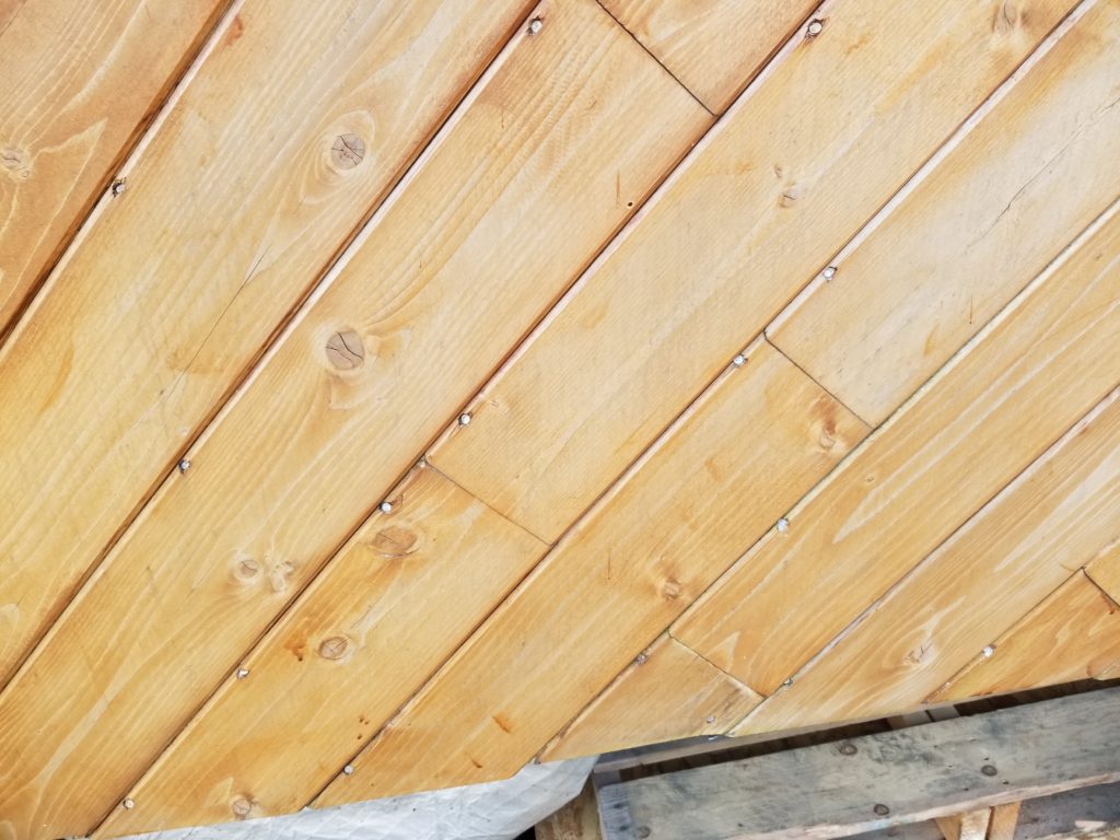
And lucky again! At least so far, I didn’t find any studs, so cutting into the wall for the pipes wasn’t particularly challenging. The 3″ of closed cell foam (green) took some excavating to get it outta there, but me and Multi Max (this thing has saved my bacon so many times) and a few other tools not normally used for this kind of task make relatively short work of getting from the inside to the outer skin. The long drill bits were to extend the location of the hole, marked on the inside of the house, all the way to the exterior wall. You see, there’s this big rectangular clearance, but the very end is a pair of precisely-located circular holes that the pipes pass through. This will make a little more sense in a few moments.
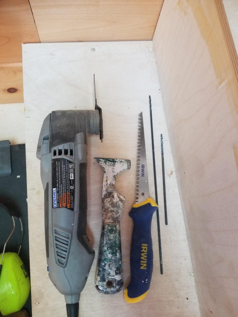
My best friend, Multi Max with a carbide plunge cut blade, a paint can & roller cleaning tool – especially good at picking and prying out closed cell foam insulation, a wallboard saw, also good at cutting through the foam, and a couple of very long 1/8″ drill bits.
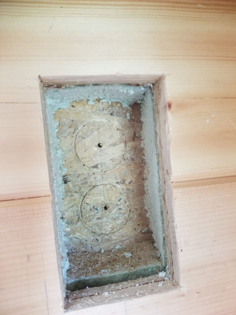
It turned out that the holes drilled for the centers of the circles from way back inside the house weren’t 100% level so their relative positions on the outer wall wasn’t quite right. I checked. And I checked again. And again. And when I was convinced the bottom hole was good and the top one had wandered, I measured relative to the bottom one and set a new location for the top one. Then I just scored it with the hole saw to verify. Drilling it out from the inside would probably blast through the siding and tear the wood as the hole saw broke free. It would be better to complete those holes from the outside, in. So I took those long bits, planted them firmly on the divot for the hole saw center drill goes, and drove them through the 1.5″ or so of material to get to the outside. Not nearly as much opportunity to go wildly off when it’s only 1.5″. Then up a short ladder on the outside and drill it through.
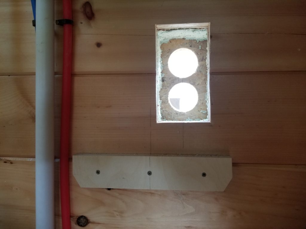
Presto! Nearly perfect. Definitely good enough. I am pleased. At least something was going well today! Now to mount the sleeve, install the furnace, and check the alignment.
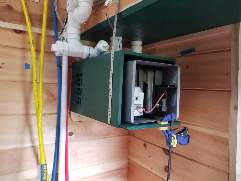
There it is, furnace (sans front grille), sleeve (green box), mounted to the cleat and temporarily secured with a pipe strap. Now you see why the cleanout (pipe cap with blue smear around it) is angled the way it is. And it’s 61 inches from the bottom of the sleeve to the floor. Okay! So, how’d I do???
It was a dark and horrible photo, so you don’t get to see it, but huzzah! The alignment seems good! Okay! Time to fit the exhaust and intake pipes, caulk up the outside cap/grille, and move on to running the gas line for the furnace!
Except not.
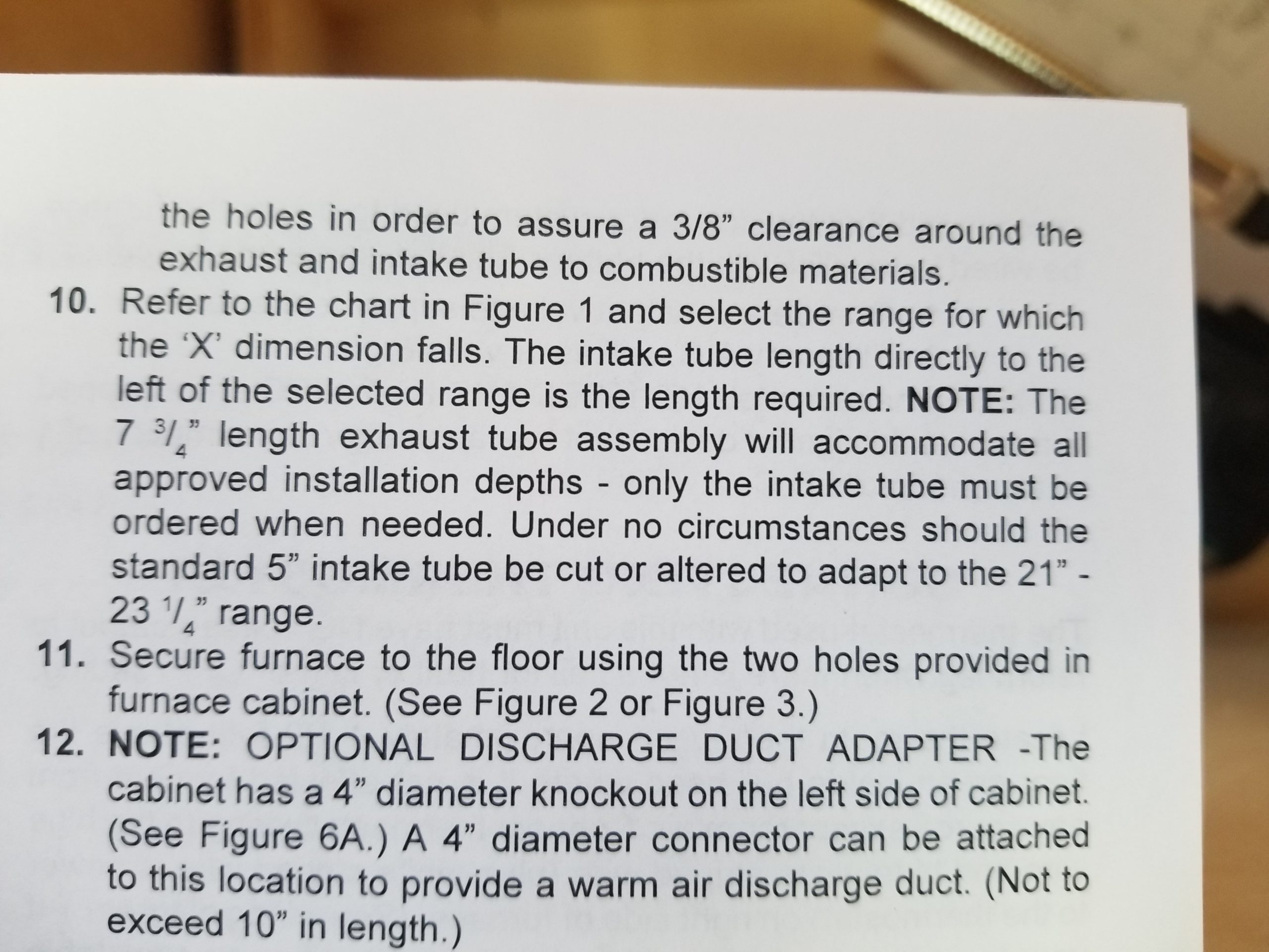
I present to you exhibits A and B. Click to zoom. On the left, an excerpt from the installation manual which speaks of the 7-3/4″ long exhaust tube (item 10) and that all approved installation depths are accommodated by this one tube, which telescopes onto the corresponding member of the furnace to take up whatever depth allowance is not necessary.
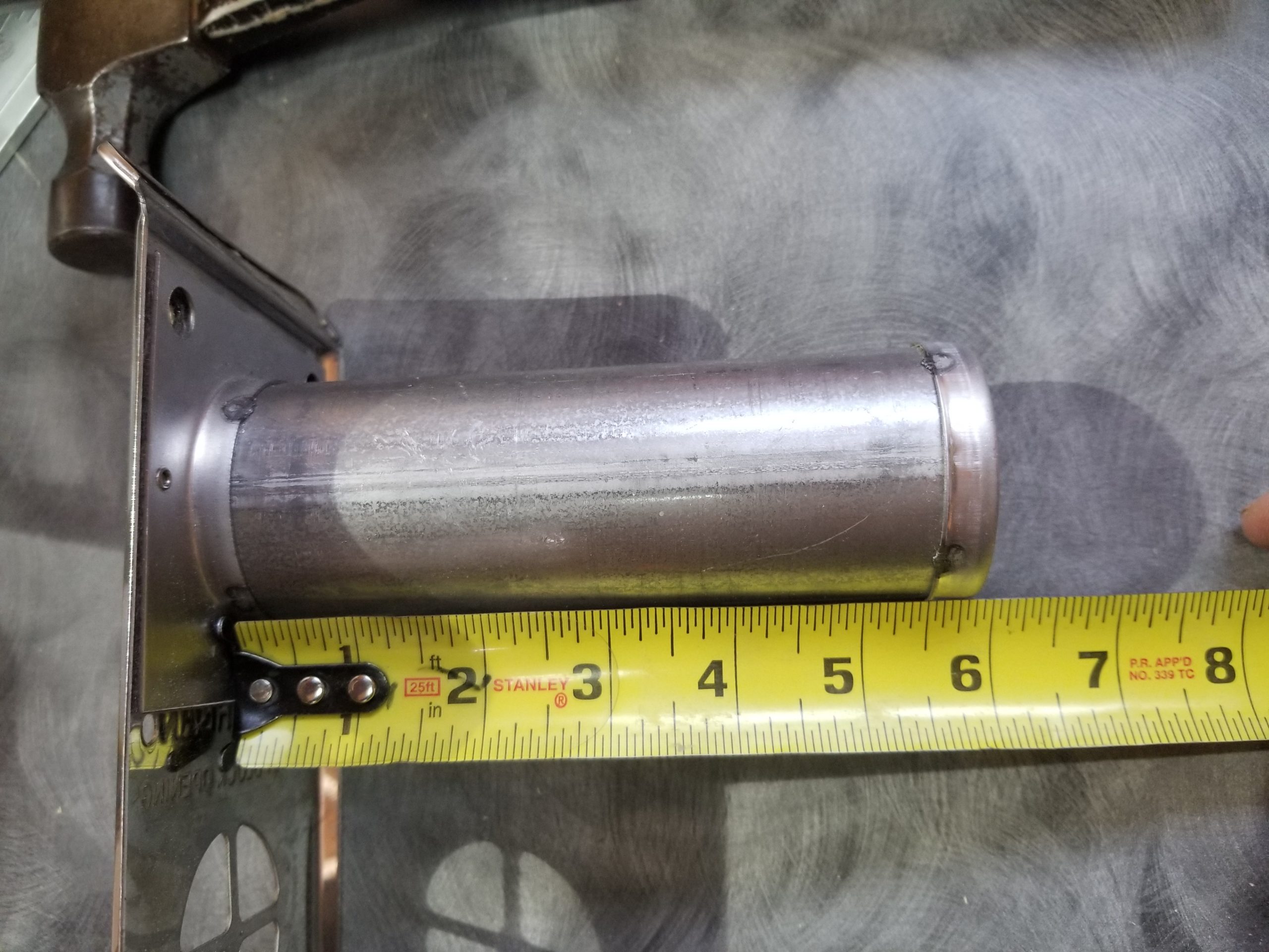
I now direct your attention to exhibit B, the exhaust tube and cap face. Please notice how it is very nearly 6″ long. Please also notice that very nearly 6″ long is not at all 7-3/4″ long. My wall is 6″ thick. A 7-3/4″ long pipe would easily transit the wall and telescope nicely onto the furnace port with well over 1.5″ of overlap for a nice, secure fit. Except the pipe is just under 6″ long. It almost touches the thing it’s supposed to overlap by more than an inch. No bueno. The manual clearly shows that this unit can be installed through walls up to 6″ thick, as long as one buys the extra-long intake tube, which I did. See item 10, above left, where it says “only the intake tube must be ordered if needed”. It was, and I did, and it’s 7-1/4″ long and mates nicely with its corresponding part in the furnace proper. Not so much this 5-7/8″ long exhaust tube. Shit.
I have written to the vendor, who was happy to check his stock and found that the other two units he had both had 6″ (nominal) exhausts. It seems the manufacturer has changed the standard part without having changed the documentation. I have written to the manufacturer, too, but have not yet received a response (it’s been only 1 business day as I write this). The good news is that the unit is rated for being let into the wall up to 2 inches, so if I care to open up that rectangular pipe clearance hole to accommodate the entire furnace body section, I can get up to 2 inches reduced and then the exhaust will fit. My extra-long intake pipe might be too long, but then the stock one that came with the unit will probably do it (or I’ll cut the other one). This would also mean cutting the sleeve by a corresponding amount because it has holes carefully cut in it to match features on the furnace body (gas inlet, wiring access, air supply), but okay, that’s just a visit to the table saw. Doing this significantly reduces the insulation in effect at this location, but it’s not terrible, especially considering what happens here is fire makes air hot. I’m hoping the manufacturer has the 7-3/4″ length part available, perhaps from “before”, but frankly I seriously doubt it. I’d like to see them take some responsibility for my trouble, though, at the very least.
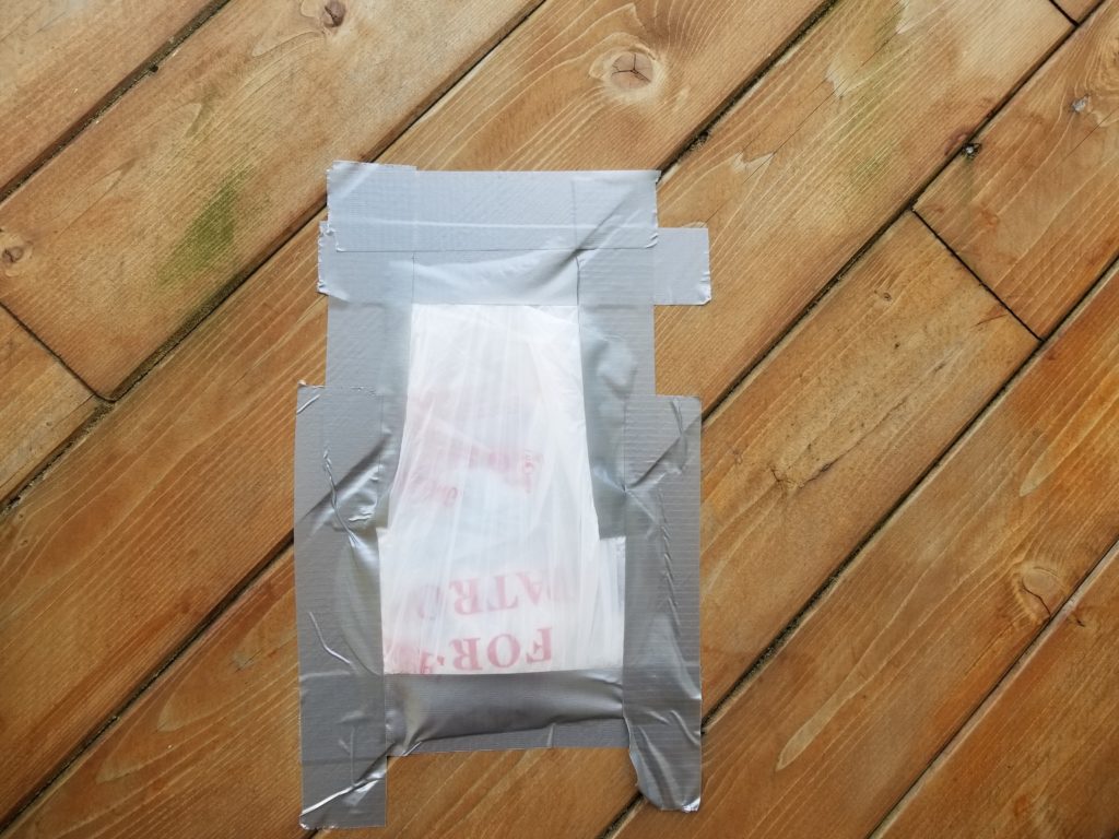
Meanwhile, a bandage keeps the critters out while I wait.
I was GOING to complete the gas run from the loft to the kitchen, which passes through and tees off to feed the furnace, but without being certain what’s going on with the furnace, I didn’t want to commit the gas line plumbing there. So it waits until I have a resolution from the mfr or I decide to go with plan B (letting the furnace into the wall a bit). Still, I could hook up the water heater and get going with the stove — the ends which will meet at the furnace — and so I did. Here’s the CSST (yellow flex line) coming across the utility loft, meeting some pipe, and the cutoff/feed for the water heater.
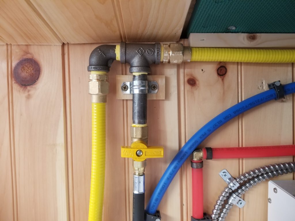
Why the transition to black pipe? Simple: the corrugated stainless steel tubing (“CSST”) system doesn’t actually have fittings like tees and such. It’s meant for trunk lines. If you want to tee off it, you need to first transition to some other pipe. In this case, I’m using standard 1/2″ black “iron” (it’s steel) pipe because (a) it’s common for gas work and (b) it is especially stout. This lets me strap it securely to the wall such that any torque on the cutoff valve (yellow handle) won’t be communicated back to the CSST, which is not at all structural. The black pipe is quite mechanically strong, so this makes a bunch of sense. With the tee in place, the route for the CSST would be too sharp to turn (it takes a relatively wide bend radius), so a black pipe elbow comes first, then the transition back to CSST. Why not black pipe all the way? Easy! The CSST is flexible and thus can be readily routed around obstacles, turn (gentle) corners, all without needing fittings of any kind. There’s a long run from the Propane Porch, across the T.H.R.O.N.E. Room, up the corner into the utility loft, across the ceiling, finally to here. That’s about 20 ft of length and three direction changes. All I had to do was pull the CSST through and tack it down with some clips. No fussing with pipe tape, heavy wrenches, heavy pipe, and hoping to get things ramrod straight because the pipe is and it’s not forgiving. No, thanks. I’ll take the CSST and the minor inconvenience of transitioning in and out of black pipe for access. It’s like PEX for gas … almost 🙂
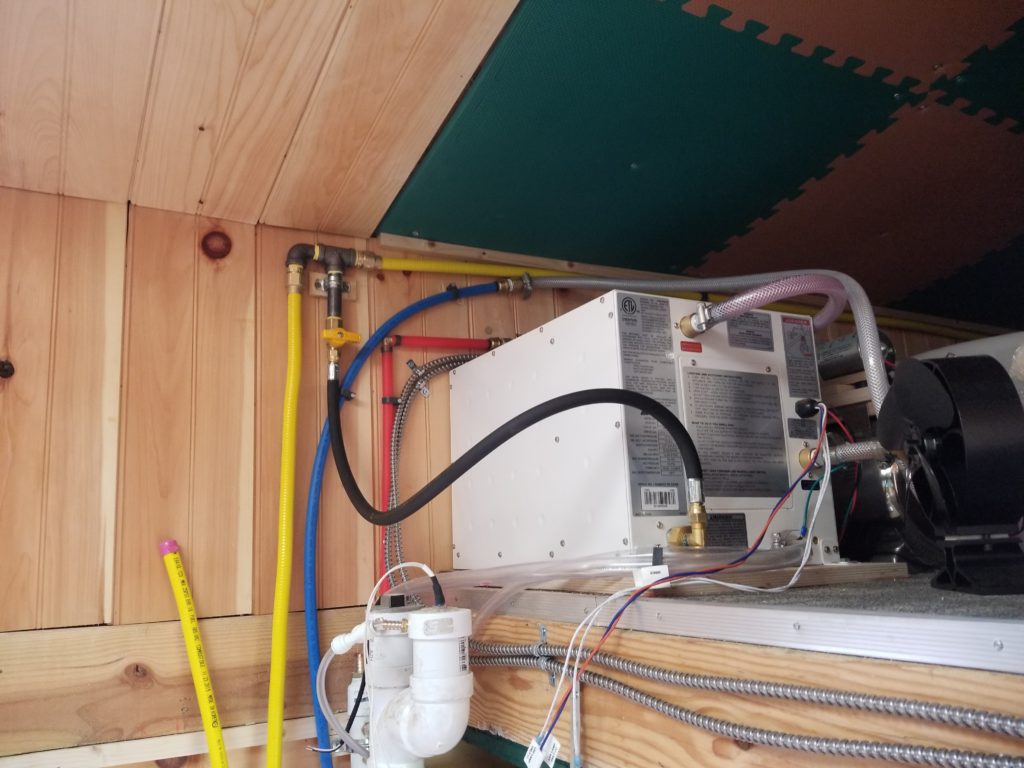
Add a feed hose and now the water heater, if it also had its electric hooked up, could heat water. That other CSST line is the tail of the run from the stove. It will be trimmed to meet a tee for the furnace when the time comes that the furnace’s final placement is known.
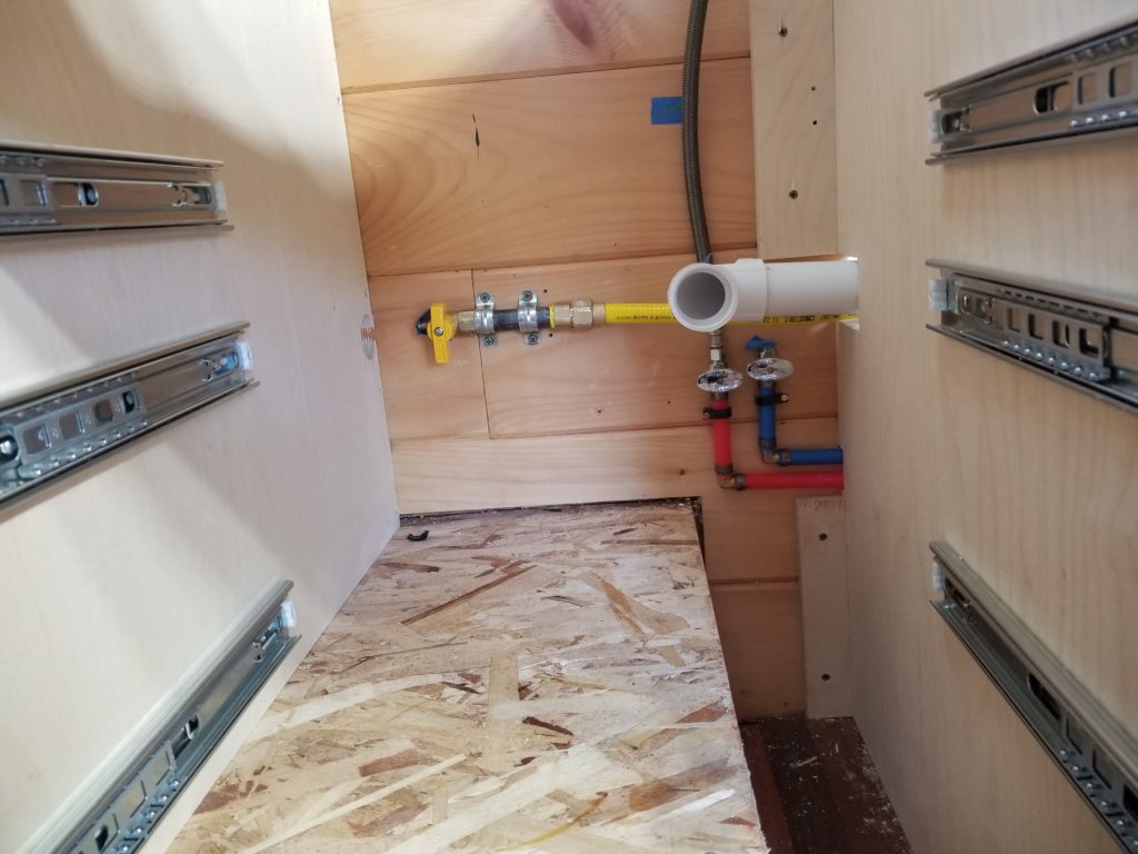
Speaking of the run from the stove, here’s the other end of that. It’s under the sink cabinet (hence the sink drain in progress — white plastic pipe). In order to accommodate a length of black pipe before the cutoff valve – again to secure it to the wall and prevent handle torque from being communicated back to the CSST fitting, and to allow for the limits of bending for the CSST, the line had to be placed HERE. I’m glad I was smart enough to resist the temptation to install the sink first – it would come down as far as that piece of blue tape on the wall, forcing me to work face down, arms fully extended, over a 10″ ledge (that OSB corner you see there) — that would be really unpleasant. This way I have decent access from the front as well as the top. As it turned out, I had run the water lines (blue & red) FIRST and had placed them rather logically more toward the middle of the cabinet. That wound up demanding too much bend of the CSST, though, so I had to move them all of 4 inches to the right. At least PEX is especially easy to work with and shortening the supply feed was quick and painless.
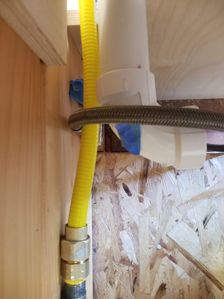
Here’s a top view, showing the bend of the gas line to get around the water supply (braided hose standing in for the lines that go to the faucet). You can see that if the water supply were closer to the CSST/Black pipe junction, a lot more bend would be required on the gas line (yellow), potentially compromising the fitting. Hence the relocation of the water to the far edge of the cabinet.
I bought a bunch of rubber hookup hoses to connect the cutoffs to the various gas appliances. Good for the furnace and water heater, but a poor choice, it turns out, for the stove/oven. Why? The hoses are rated for about 120F. It’s pretty likely that the cabinet behind the stove will get hotter than that — not hot enough to burn anything, but definitely hot enough to compromise a rubber hose. Okay, then, conventional copper tubing it is. Time to buy a flare tool and learn a new skill 🙂
This whole project is being done rather on-the-fly. No plans. I do, however, occasionally make sketches or schematics so I can keep track of my intended solutions to any given problem as I’m putting it together — or composing a shopping list. My “plans” usually look a lot like this:
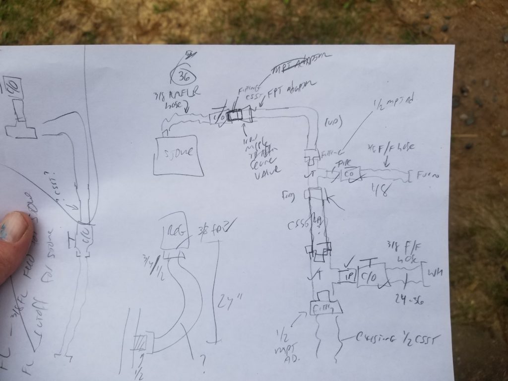
Just enough of my horrible handwriting to show the fittings, valves, transitions, materials, and distances.
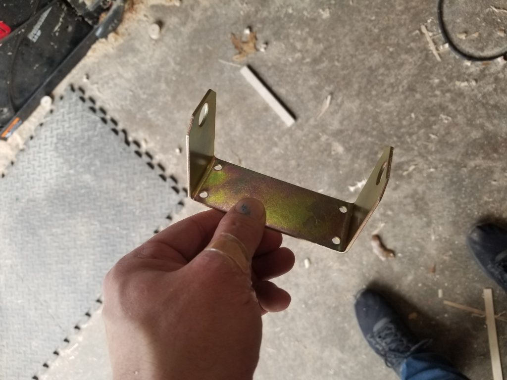
Hey, as long as I’m hooking up propane, how about actually finishing the work on the Propane Porch side of things? Yes, let’s. I open the box for the auto-switch-over regulator and find this mounting bracket, intended to adapt the regulator to a pole/rod. I have no such feature. I want to mount it to the wall. I briefly consider bending the bracket ears flat, drilling them for smaller screws, and using it that way, but think better of it and instead transfer the holes to a block of plywood and make my own mount.
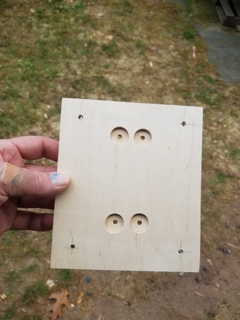
It’s nothing fancy – just a block of plywood with holes and counter-bores to accept some washers. But it’s the right thing to mount the regulator to the wall. And so it is done.
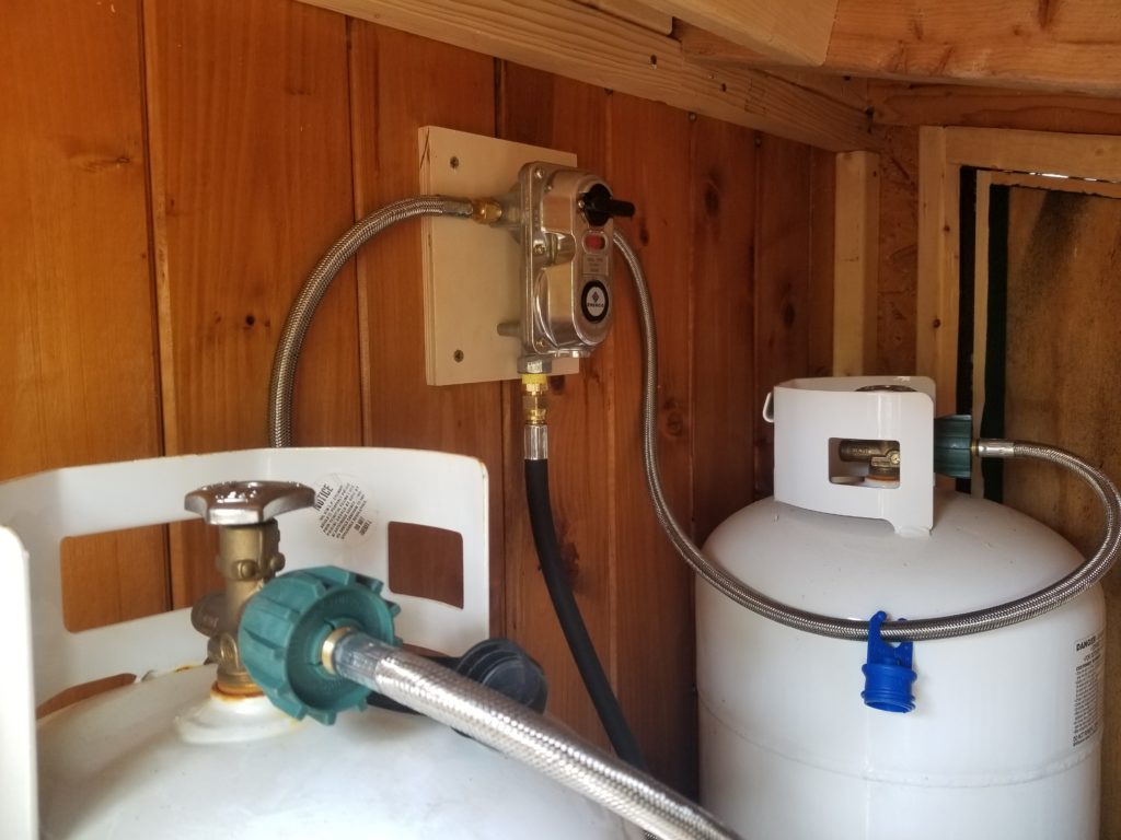
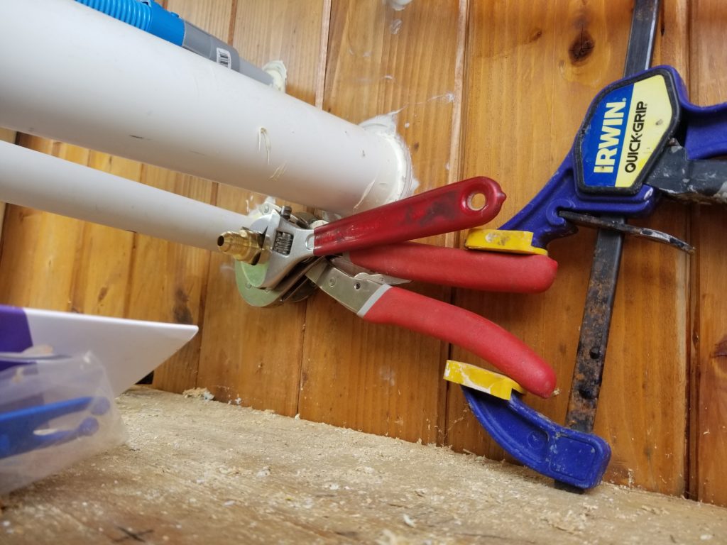
One last bit of hookup – the regulator output (bottom, black hose) to the pass-through flange at the end (well, the start, really) of the CSST line. But now there are water supply lines and electrical conduit crowding that area rather much. I had to get creative to install the flare fitting into the stub on the flange. One wrench to hold the flange in place. One clamp to hold the wrench in place. Another wrench to actually tighten the new fitting. There was just enough swing to turn the fitting maybe 1/8″ turn at a time, but it was enough and it got done. Never underestimate the utility of a clamp. So much more than just holding two pieces of wood together!
Okay! Propane Porch is now DONE. Well, I want to install some straps to hold the tanks securely, but all the hard part is done.
Now, while (at the time) I wait to hear back from the furnace vendor about the exhaust tube, what else can I work on? There’s no shortage of stuff, of course, it’s always just a question of what to choose. In this case, I decide it’s time to mount the wood stove properly to the hearth. To do that, I’ll need some hanger bolts (half wood screw, half machine screw), and some pretty precise positioning, since the stove must be directly below the flue and the mounting holes in the stove base are small, so not a lot of wiggle room if I get the bolts set wrong. I gave it some thought and came up with a solution that absolutely guarantees the bolts will fit through the holes in the stove base. How? By driving them into the wood through the stove base in the first place, never moving the stove away afterward. That’s how. And this is how I did that.
First, some time ago, actually, I traced the bottom of the stove as placed perfectly beneath the flue. That outline is marked on tape on the hearth already. Next, dismount the stove and affix a paper template to its base. Cut to match the outline perfectly. Then punch holes through the stove base’s own mounting holes, transferring their location to the paper.
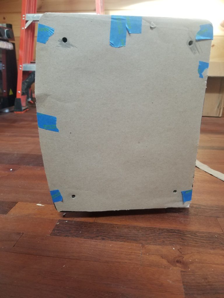
Then align the template (removed from the stove base) to the hearth.
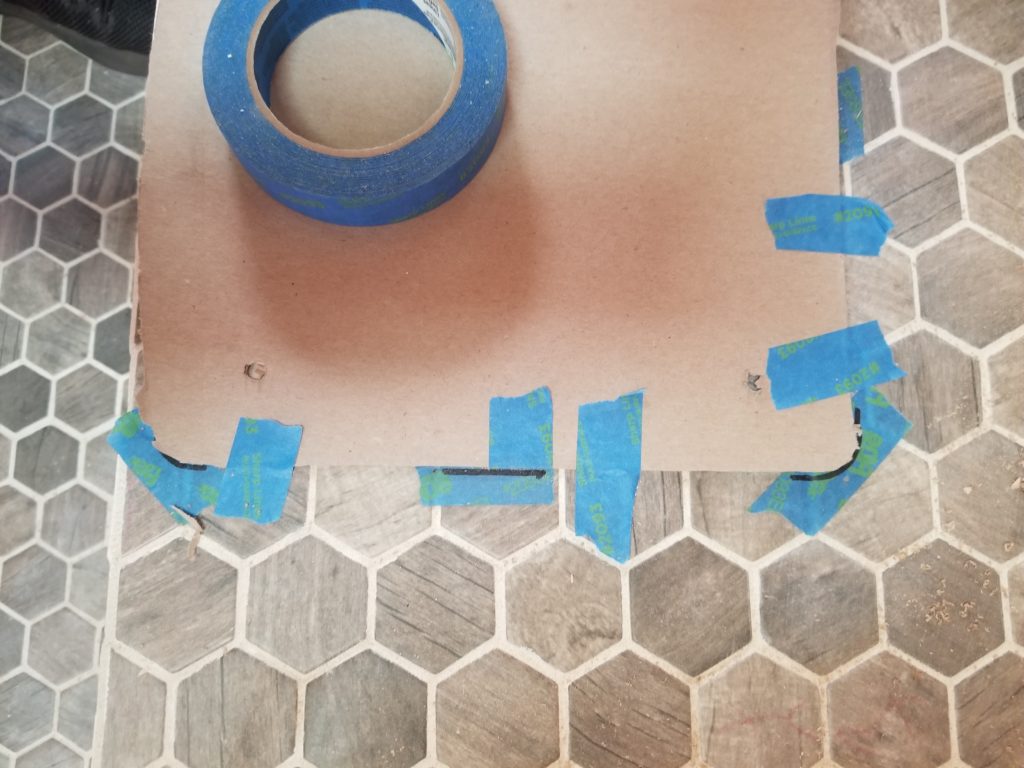
And now I know exactly where the holes need to be. But I’m wise enough to know that drilling tile is not an exact operation. It’s easy for the bit to wander a little. And if it does, the bolts won’t line up with the holes and I’ll have a big problem. However, I’m not actually drilling into the tile so much as through the tile. The bolts will anchor in the plywood below the cement board below the tile. So it really doesn’t matter where the holes in the tile are — or how big they are — as long as they include the location of the bolt. Okay, then! Those 1/4″ bolts will pass through 1/2″ clearance holes in the tile.
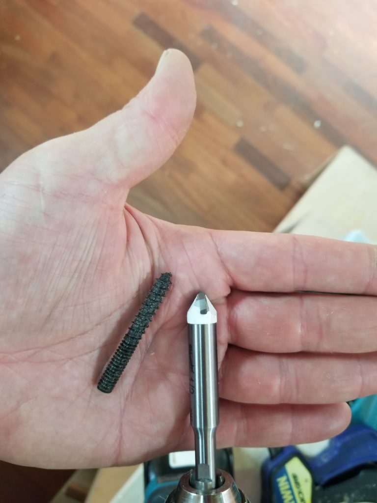
A few moments of quality time with a black Sharpie to transfer the hole locations, then a tile-eating 1/2″ drill bit to get through it, down to but not into the plywood, and I’m ready to start setting the bolts for real. Drill bit (right) is twice as big as the bolt (left), allowing for some imprecision.
The usual way to drive such a bolt as this is to thread on a machine nut on the machine side, then jam it all the way down against the wood screw threads, then with a wrench or a socket, use the nut to drive the wood screw into some wood. After that, back off the nut, put whatever you mean to attach with the bolt over the bolt, and hold it there with the nut, returned to the machine threads. The thing is, in this case, the depth of the plywood into which this bolt is going is too far away for this to work. I need to drive the bolt from the end, not the middle. What to do?
THIS:
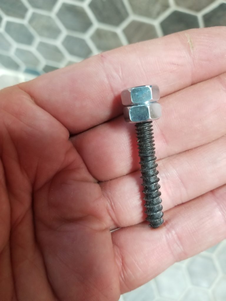
Two nuts jammed onto each other, effectively creating a hex head lag bolt out of this thing. If I am careful to have the two nuts offset a little, the second nut will prevent my socket from sliding down the whole length and allow me thus to apply some pressure with the socket to help start the screw.
The angular offset of the second nut does not align with the socket, already aligned with the first nut, giving me solid purchase on the impromptu bolt head.
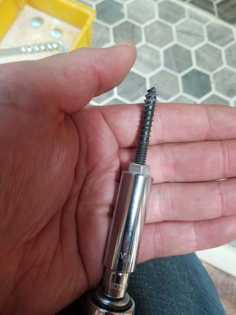

I put the stove back on the hearth, locate it to the prior outline (template is long since gone), then simply set the bolts through the stove base, into the clearance holes. Now, with the ratchet, applying some downward force (because I can!), I screw the bolts into the plywood with the stove already in place. This guarantees the stove will fit over the bolts because it already is over the bolts. Repeat for all four, remove the jam nuts and finish the mounting with a washer. Done. I was pretty proud of myself for figuring this process out, if I do say so. And I do.
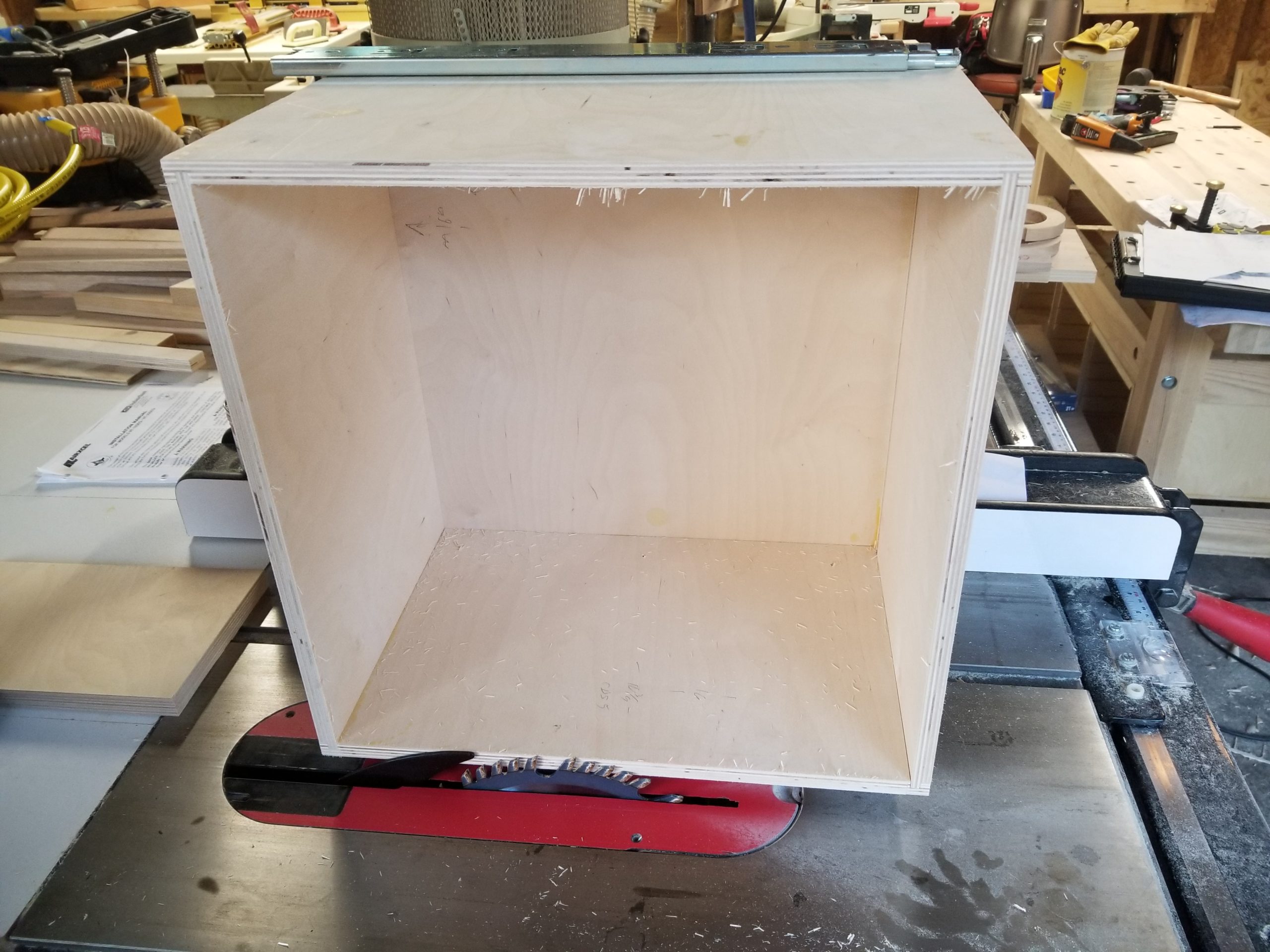
So that’s furnace rancors, stove anchors, and holes in sides. What about drawer slides? Well, if you were astute, you would have seen them in the base cabinet pictures apropos of the sink and cookstove gas story. Not much more to say – I talked about the drawers last post, as I realized the furnace sleeve was basically built like a drawer, so I might as well just build them all. So I did. And now they’re mounted (but don’t have decorative fronts yet).
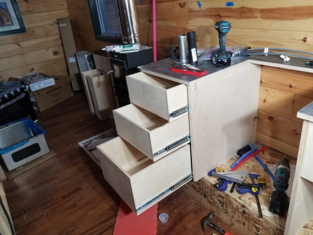
They are all full-extension to the depth of the bottom one. Shown here stairstep for composition purposes only.
Sometimes, despite one’s best efforts, things don’t quite fit right… and thus a visit to the table saw is necessary to fine tune the fit of a drawer.

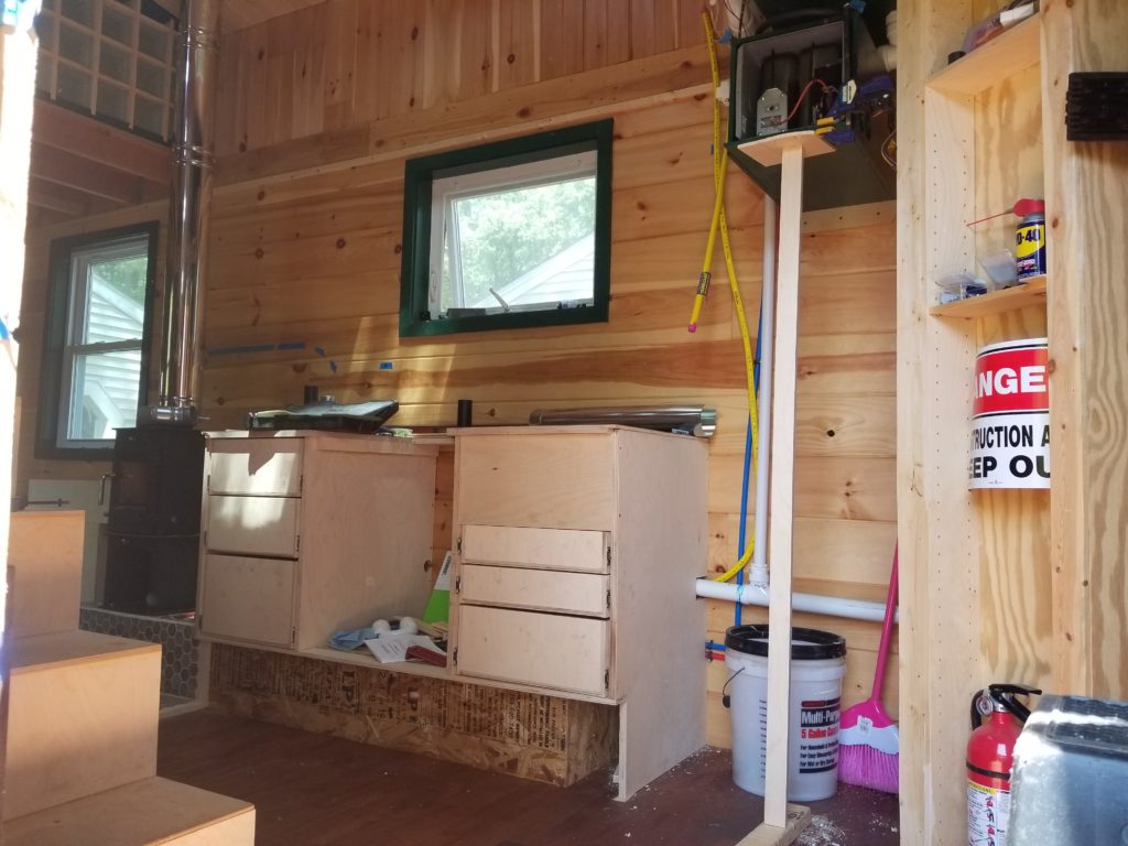
The drawers under the sink (right) are shallower, since the sink drain prevents them from being full depth of the base cabinet. There will be a long skinny one in that odd little pocket between the wheel cover (OSB box under the cabinets) and the right side of the base cabinet under the sink. The fridge will go where that T-brace is holding up the furnace right now.
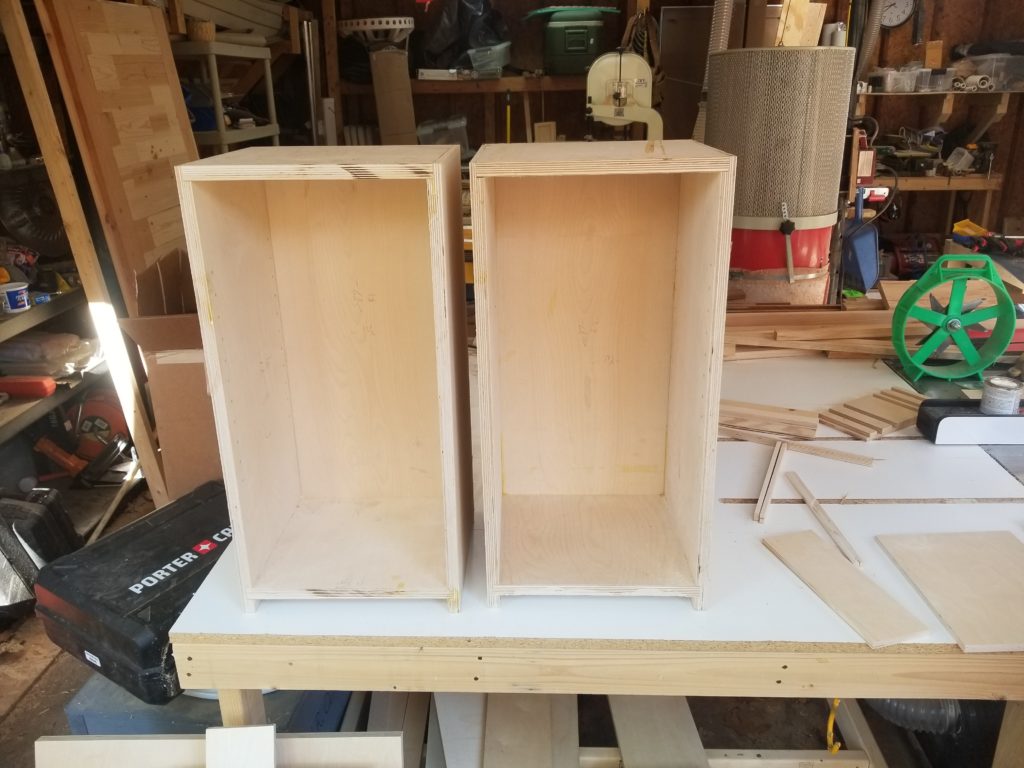
I also built the cabinets for the wall, but those won’t get installed until all the work below them is done so access to the base cabinets is less obstructed.
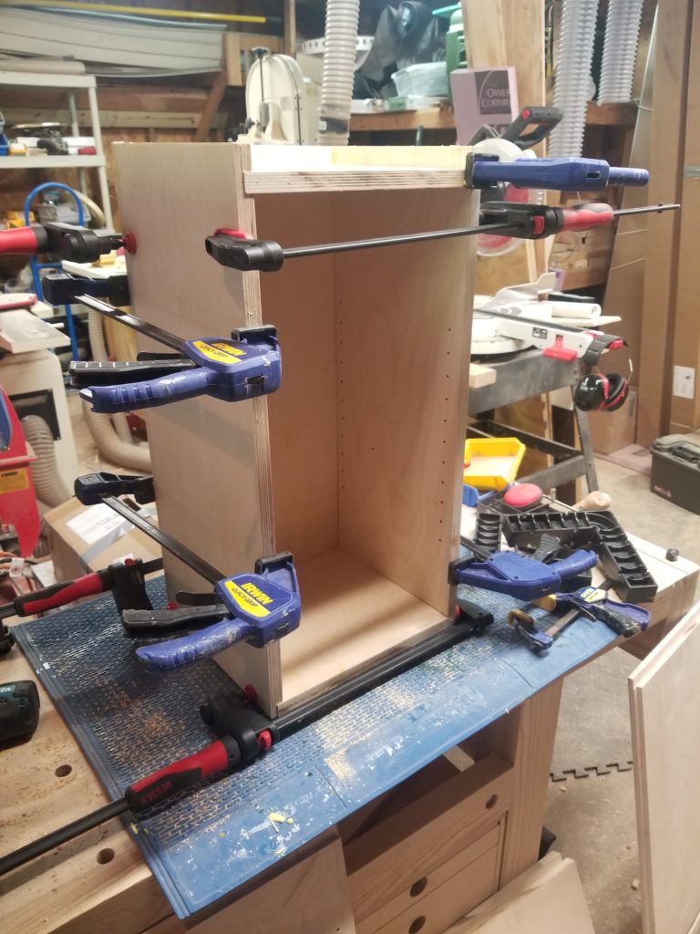
I’d admit that one of my two cabinets isn’t quite square… I goofed during assembly and didn’t catch it…
But, honestly, when the square one and not-square one stand side by side, you can’t tell them apart, so I guess it’s not so bad 🙂 And anyhow, there’s precious little in this whole house that’s flat, square, or level, so why start now? 🙂
As you can see, it’s been a busy couple of week since my last post!
There was actually a little more work on the wood stove, too! There’s an outside-air intake that needs to get its outside air. I didn’t want to drill that until the location of the stove was absolutely final (i.e., bolted down for real), lest things shift a little and the ductwork not align well with the hole. But that also means drilling the hole when the stove is in place. This was another one of those moments when I just got lucky about clearance. Every now and then (and evidently twice this week), the randomness lands in my favor.
Just enough room to get my drill and the hole saw started behind the stove.
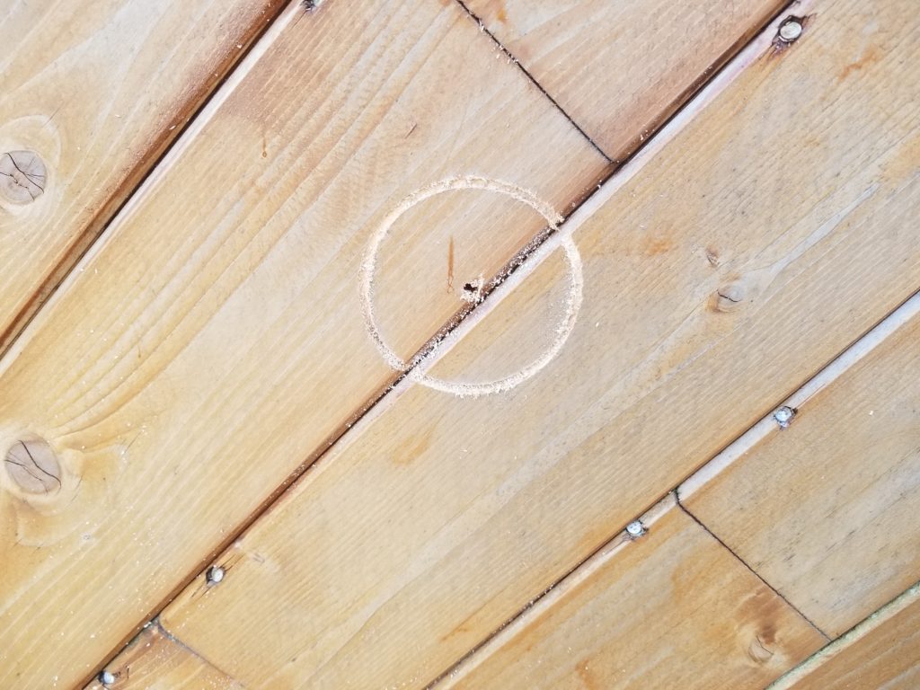
I didn’t actually finish this hole, though, since I wasn’t ready to dress the exterior that day. I did drill a pilot hole through so I could finish it from outside. Of course, the pilot hole was mostly invisible…
Can you see it?
How about after I quick touch it with the hole saw?
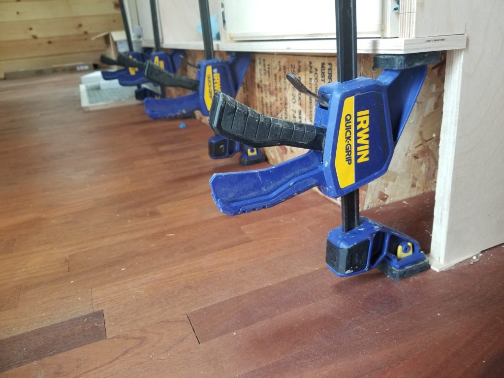
I’ll return to this later. The last little bit of work from this session was this trim board. Remember I said not to underestimate the utility of clamps? Right. Don’t. These clamps have a special feature by which one of their jaws can be reversed such that they become spreaders rather than clamps. This is very handy when one needs to push, rather than pull, as in the case of gluing on this trim board which is too close to the floor to get any sane fasteners into it. A little glue and four spreaders gets it done easily.
That’s where things stand today. I leave you with this dust mask, who happened to have an especially derpy expression when observed laying on my bench, upside down (the “mouth” is the nose bridge for the mask).