There’s been a lot of action since the last update. The weather has warmed up a bit so I could get in some late-season work before winter really sets in. I thought we were there already, with temps in the 30s and slightly below just a week ago, but we had a bounce and who am I to turnip such an opportunity?
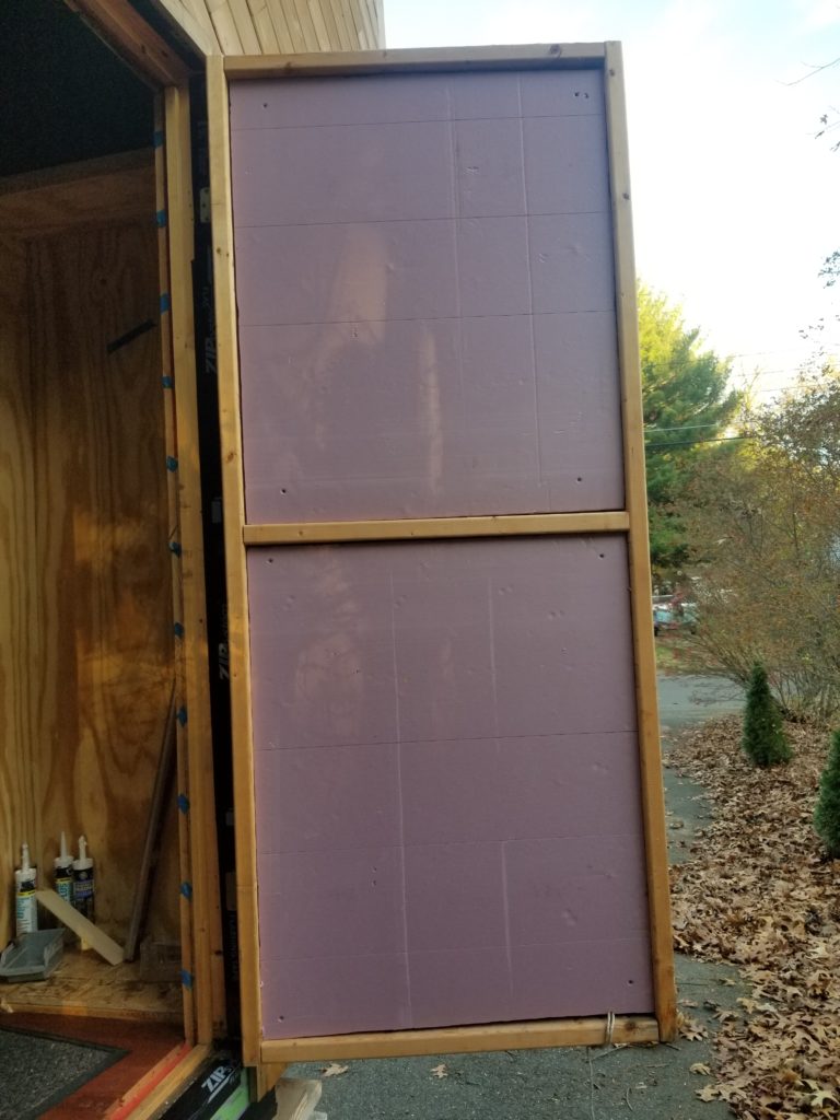
Still, winter is coming and now that my power system is operational, and more importantly, now that $12,000 worth of batteries are installed in the HomeBox, it has become important to me to keep the place from freezing over winter. The batteries won’t really like to be that cold. I put a temporary electric heater to take the edge off (it’s set to just 45F) and given the really awesome sprayed-in insulation, I think it’ll be fine. Still, I have a remote temperature sensor in there so I can know for sure and the 7/16″ OSB “construction door” definitely isn’t winter-worthy on its own. So I helped it a bit. A few scraps of 1.5″ XPS foam left over from insulating the floor so long ago now put to good use (thanks, new hot knife, you made this easy):
My priority for this work session was to get the water system tested, so I could FINALLY install that tub and wash sink and get the T.H.R.O.N.E. Room done this season. That’s my goal. To get there, a lot of things had to be done first, most of which are done, but I need to know the pipe work behind where the tub will go is itself non-leaking because getting to it later would be a royal pain.
Before I can test the water system, I do need to get electricity to my pressure pump. That’s this junction box right here.
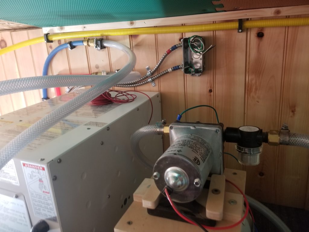
Looks innocent enough, yes? Just an ordinary junction box, pretty close to the pressure pump (foreground). Run a couple of wires, then done. Easy.
Look closer. See the wainscoting on the wall. Look down. You can see where it ends. Look up. You can see where it ends. That junction box is what, 4 inches high? All of a sudden you realize just how much space there isn’t right here. There’s plenty of room for the box and the pump and such, but what about a 6’1″, 250# person to do the work? Where do we put him?
Here I am, sitting on the edge of the SUL, pointing toward that junction box. Notice how much room I don’t have for my head? And this is with my legs over the edge of the loft. Actually addressing the junction box, I need to assume positions this nearly-50-year-old body is not meant to assume.

For funsies, I measured how far of a reach it was from the front of where I could manage to get my body to the junction box. The wire stripper is about where my knees were, 29 inches from the wall. My favorite: working at arm’s length, on my knees. Hey, wait, how is it I’m going to not fall over? Well, if I had Phenomenal Cosmic Core Strength, maybe that way. But I don’t. Thankfully, the water heater (big white box) and freshwater tank (other big white box) were close enough by that I could lean my elbows on them for support.
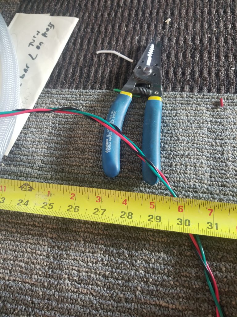
Of course, that made actually doing the wiring work all the more difficult.
But as long as we’re looking at this picture, let’s also take a moment to appreciate the 3-braid of the wires. There are two circuits in the junction box – power for the water heater and power for the pressure pump. To keep the wires tidy and make sure they stay together, I could either use wire ties every few inches or just do this, which for reasons I cannot explain, just made me happier.
Because I am occasionally a masochist, I was curious about just exactly how much headroom I didn’t have, so I measured it.
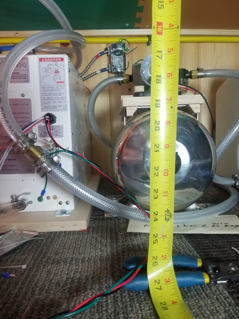
27 inches.
Sitting upright, comfortably, it’s about 38 inches from my butt to crown.
Have I mentioned lately how working on a tiny house is considerably harder than working on a full-sized one?
This is what I mean when I say that.
This job would take 5 minutes from a comfortable position. At arm’s length, on my knees with no headroom and a tangle of tubing and this accumulator tank and pressure pump to contend with, considerably longer. But it got done.
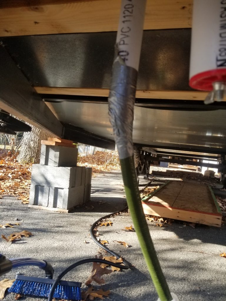
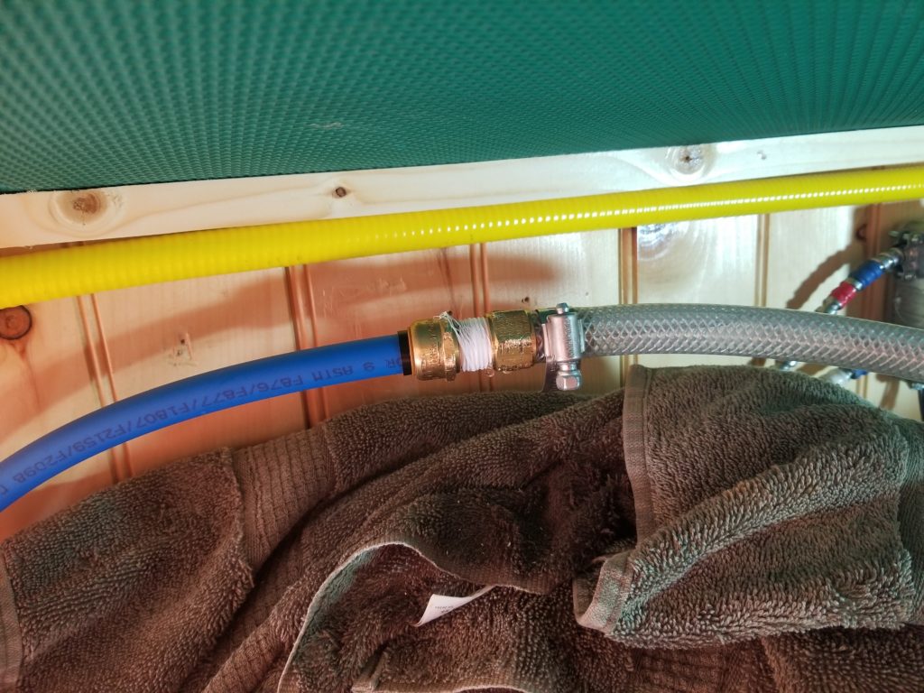
Before I can pressurize the water system, though, I need water! I do not yet have a well pump — nor a well from which the well pump would pump well — so for today’s test, the garden hose it is. A little bit of silver magic to adapt the hose to the fresh water inlet and it’s time to tank up!
The first part of the test – are there any leaks in the inlet side of things? – passes beautifully. Everything that’s supposed to stay dry stays dry. It’s low-pressure, for sure, so it’s not hard to get it right, but still, it being right makes me happy.
Now double-check that all the cut-off valves are OFF and power on that pressure pump. It is surprisingly quiet, which pleases me. A nice low hum. I do notice that the there are some drips in a few places — most of them involving tubing and barb fittings except the plastic threaded outlet of the pump itself and another threaded fitting elsewhere. The pump’s instructions expressly said to hand tighten this connection, for fear of cracking it, and not to use teflon pipe tape. Whut? Okay, that’s what they said… so I guess the plastic fitting is soft enough it will just conform when I thread on the NPT fitting. Except not. Hand tightening definitely didn’t do it. The instructions say a half turn with a wrench is okay. Nope, not enough. A full turn. Nope. I’m starting to worry, but it’s still not holding water. I lost track of how tight I made it, but I made it as tight as I dared and it still wasn’t holding water at pressure.
So the heck with the instructions – following them resulted in leaks. I undid my pressure-side fitting, checked the threads on the pump, they seemed okay, applied some teflon pipe tape, and re-threaded on my fitting. Hey, how about that! Now it holds water at pressure. Maybe I over-did it from the start, potentially distorting the threads on the pump, causing the leak? Who knows. What I do know is that it was leaking even when very tight and now it’s not, when only moderately tight, which is much better for the long-term life of the plastic fitting on the pump. Will I regret it later? Dunno. I certainly didn’t want it leaking now though, so I did what had to be done. I suspect it will be fine. I will also buy a second pump to keep as a backup given how important it is (and how much waiting I don’t want to do without water pressure until I can get a new one if this one failed).
Tightening the hose clamps over the barbs on the tubing was enough to stanch the other minor leaks. Those are always hit-or-miss — you don’t want to over-tighten the clamps or you can break them. Under-tightening them gets leaks at pressure. Okay, a little fine-tuning and they were all fine. There was one more little leak that defied being corrected with tightness – this one, where the soft tubing met the semi-rigid PEX house piping. Unfortunately, having thought that all it needed was to be tighter, I tightened the living crap out of it and when that failed to stop the drip, loosening the living crap back into it proved to be quite challenging (on my knees, at arm’s length…). Got it done, though, observed the pipe tape I had used had shredded a bit and clearly hadn’t been applied in sufficient quantity. Awrighty, then. Clean off the tape frays, apply fresh tape a bit more generously, and all was well.
Pressure system is now holding pressure and keeping dry. I was a bit discouraged with how much leakage I had in this section of the system, but these are tricky. I’ve never had a PEX junction leak, my PVC work is almost always water-tight except when there are mechanical stresses preventing the solvent-weld from staying put as it sets, and my copper generally holds water, as well, unless there are issues like water in the pipe while trying to solder. The rest of this system is PEX, with a couple of threaded fittings at the tub filler, so I’m feeling pretty good about it. Time to try it out.
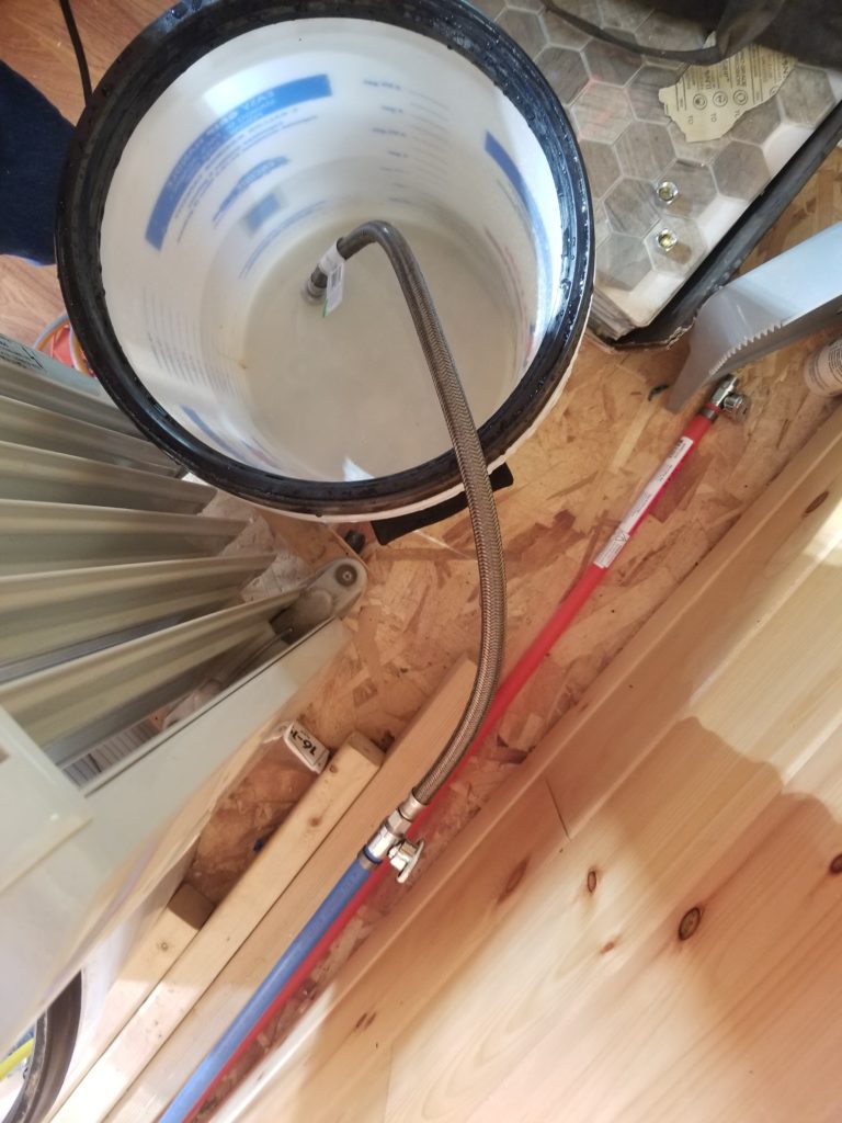
Shown here, the feed lines for the kitchen sink. All that’s here are the cut-offs, but I can test the lines by running a hose from the cut-off to a bucket, purging the lines and proving they hold water. They did.
Outside, too?
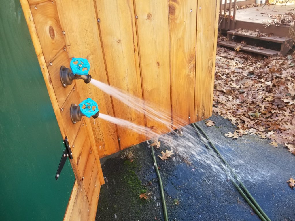
Yep. Outside, too. I have cold and cold running water! All the PEX fittings held water beautifully. The threaded connections at the tub filler, ditto. I left the system pressurized for hours and everything was fine. It’s now holding pressure overnight as a final test.
With the plumbing proven, I’m go to finish the tub installation! Woot!
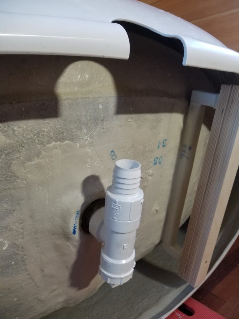
You remember those runners I built up under the tub from last time? Now I need to adapt a fitting of some kind to the drain so it can connect to that $100 length of chemical-resistant tubing.
Here’s what I came up with:
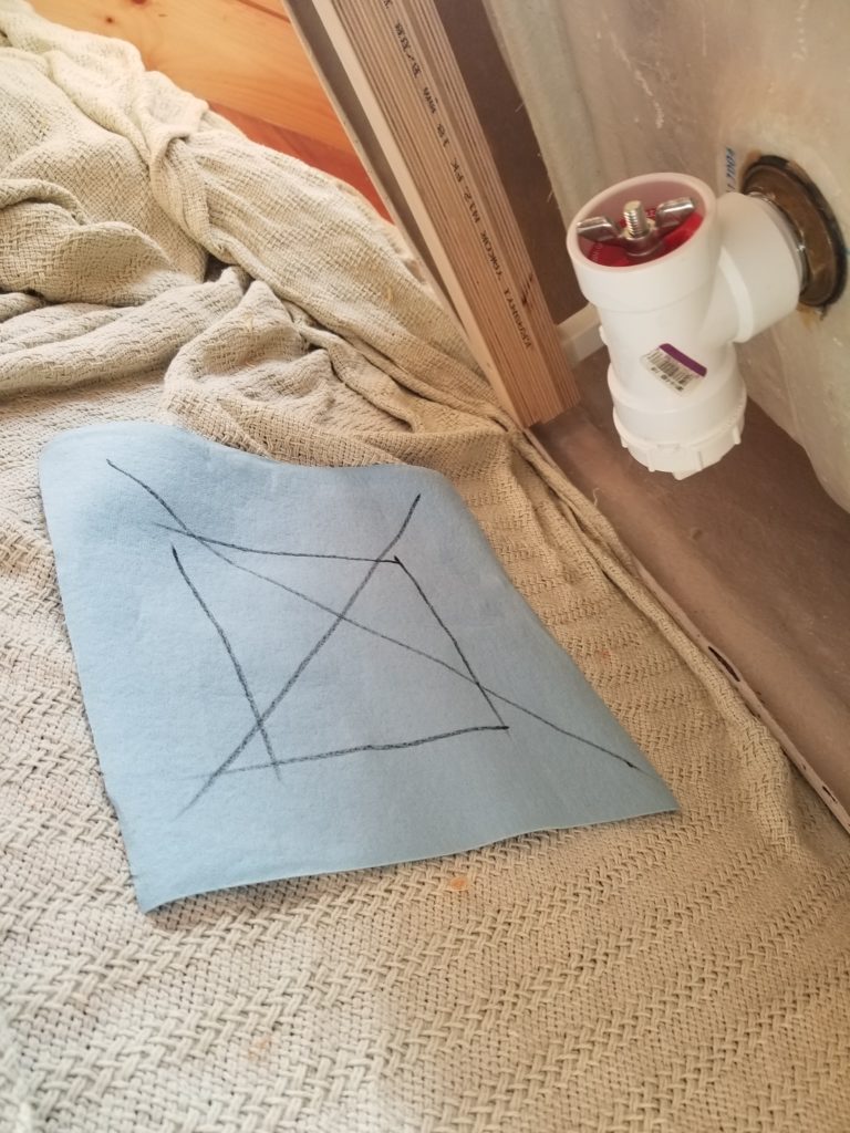
It turns out that the 1.5″ drain fitting on the tub matches the threads in this PVC tee. I don’t need a tee here, I need an elbow, but space is tight, elbows don’t have threads, and a tee can turn a corner just fine if you plug the other end of it. I do want to know that this tee, threaded onto the drain (with plenty of pipe tape!) holds water, though. There will be standing water here as part of my virtual trap, so it’s important that this assembly is water-tight at low pressure. To test it, though, means setting the tub upright, where I can’t readily observe it. What to do?
The paper shop towel (blue) will be my inspector. The sharpie lines are there to provide a smear in the case of water, even if the towel absorbs the water to the point where I can’t be sure it got wet. I right the tub, fill the drain with water, and leave it for a few minutes.
Tip the tub back over, inspect the fitting assembly – totally dry – and the blue paper towel – totally dry. I’m good to go!
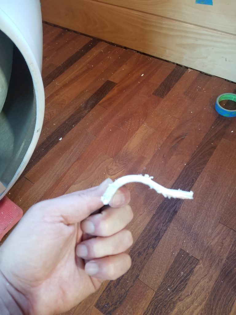
Next step, cutting the skirt of the tub so the drain hose actually has somewhere to go! It’s a fiberglass tub with a curved profile. This is not an entirely trivial operation.
Here’s the cut-out piece on edge, so you can see what I mean.
It turns out that an ordinary hole saw can do this job, after drilling a pilot for the center guide using a brad-point bit. I had my trusty drill on the very slowest speed and used the torsion brace to hold it steady.
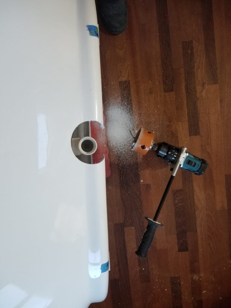
That was enough to get it done. It only bound up a couple of times and because I was going so slow, nothing bad happened. If the drill had been at full speed/power, it’s entirely possible the tub wall would have cracked when the hole saw bound. I’m very glad I had the forethought to run it low and slow. It wasn’t drilling so much as grinding, really. And that’s fine. Yes, I had my dust mask on. Nobody wants to breathe fiberglass dust.
A careful visit with the jig saw (fine blade) and some #120 sandpaper, and now I had an oversized mouse-hole for the drain hose.
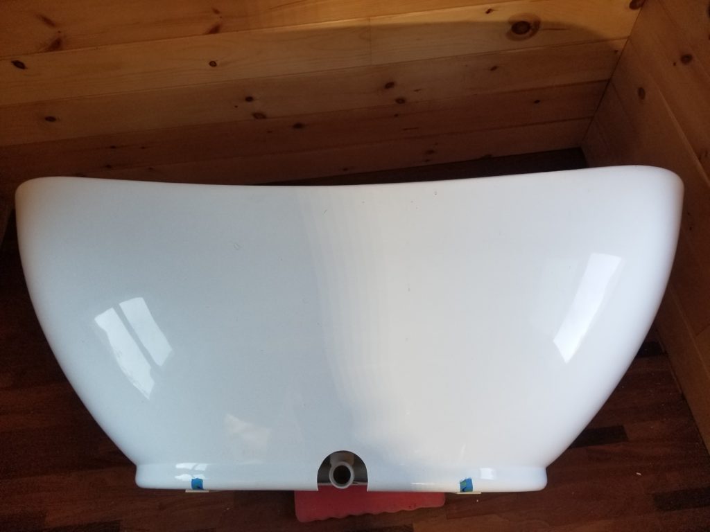
Nobody else will ever see this – it’s on the back of the tub where the tub faces the wall, but I’ll know (and you will, too!) that it’s a pretty decent-looking hole.
Just add the hose fitting and it’s almost ready!
The only thing that’s missing now is the board to which the runners will be screwed (scrod?) and then setting the hanger bolts in the floor which will be used to secure the tub assembly.
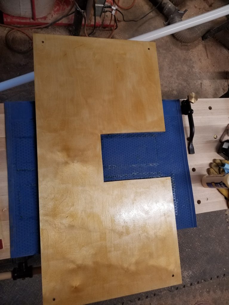
This is that board, pre-drilled for the hanger bolts. The cut-out is for access to the drain. I decided not to make two D-shaped lobes and opted instead for a single piece. This will bear the weight of the tub better and puts the bolts somewhere I can actually reach them with the tub in place. I will still need to prove it all fits, so at least one more before-it’s-final fitting needs be done, but first I need the thing that gets fitted in the fitting, and that’s this. I can’t finish this phase of the job just yet, though. This is wood and it’s going to be on the floor in the bathroom. Thus, it needs a few coats of varnish, each of which taking some time to set. Gonna be a couple of days for that.
Before we leave the subject of T.H.R.O.N.E. Room, though, let me show you my poor-man’s inline trap, as previously described:
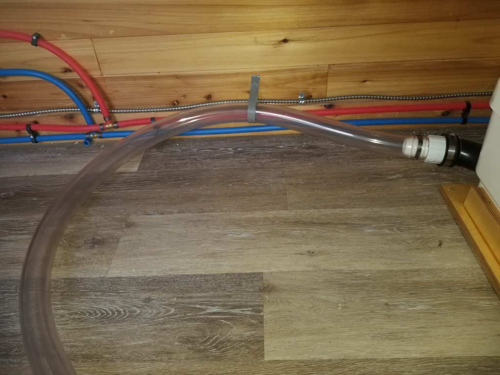
With the hump at the gray strap just a bit higher than one full tubing’s height, the last of the drain water will stay in the left side of the tubing, unable to get over the hump (which is lower than the bottom of the tub floor, so the tub will drain completely) forming a slug of water to isolate the tub from the gray water lift pump (the corner of which may be seen to the right). And that, dear readers, is how you make a stink trap when you don’t have room for a conventional trap.
But what about Pre Perc Prospecting and Four Drawers, you ask? That’s next.
This weekend also featured some digging around the homestead site, looking for a soil suitable to situate a septic system. This mostly involved the inspector guy making highly educated guesses about the soil based on the plant life he saw, then directing the excavator to dig down a bit for a closer look.
There was much digging.
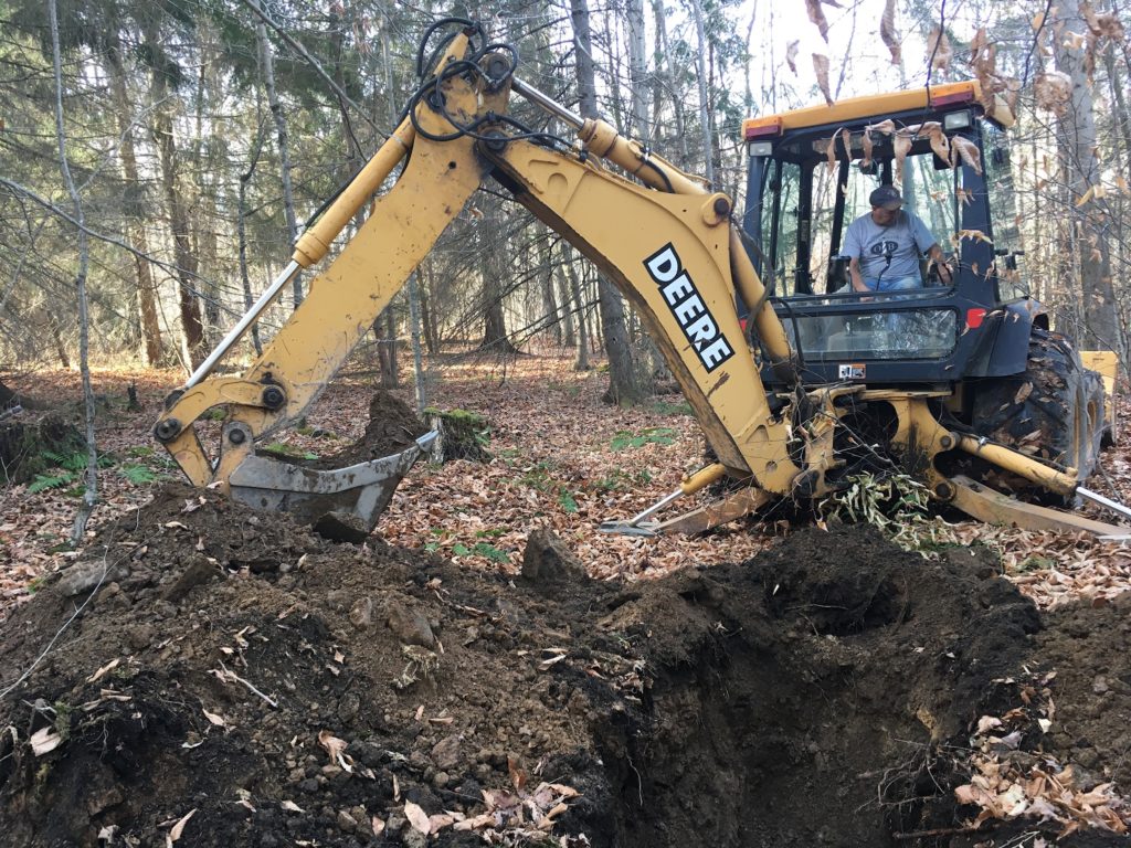
And there was much looking.
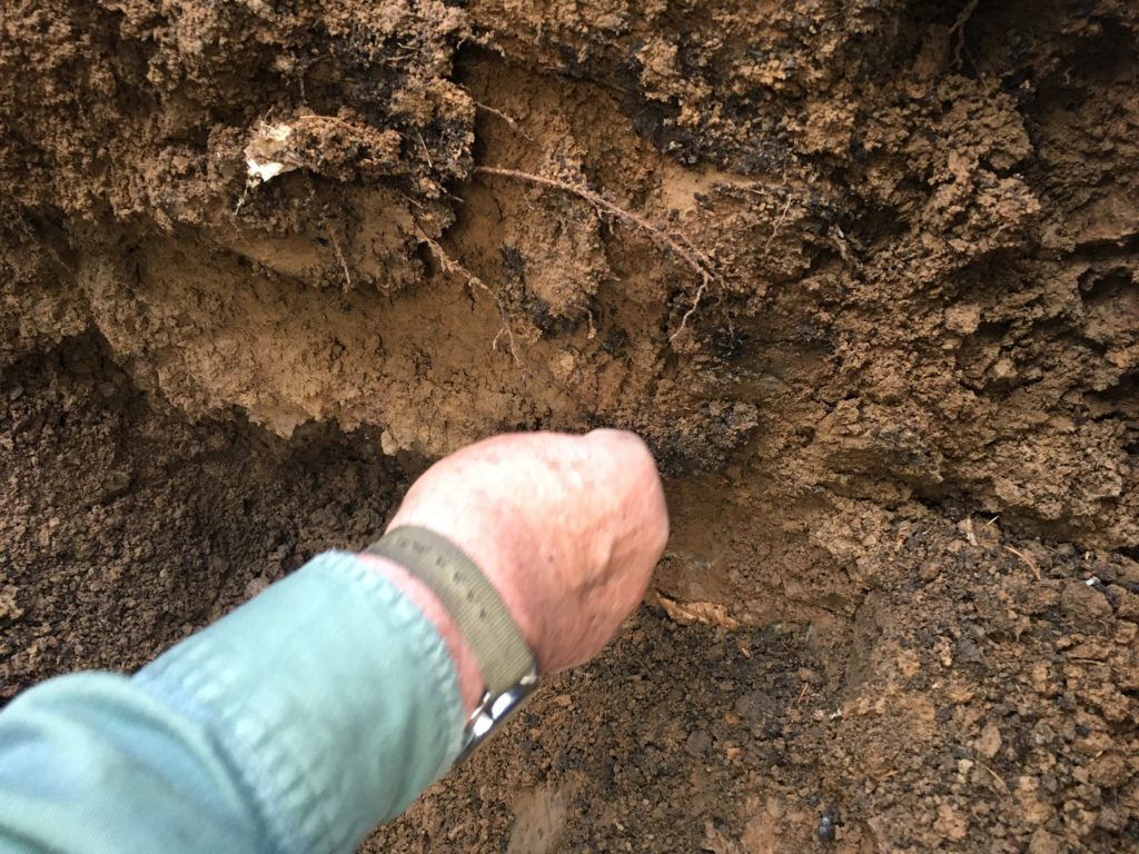
It seems the soil at the homestead site really does not lend itself at all to good drainage of the kind that’s relevant for a septic installation. Indeed, it seems there is a fair bit of clay, based on this and other pictures. That raises the interesting prospect of doing some backyard pottery — which could be lots of fun to explore — but it does complicate matters as the state insists our gray water needs to be managed like sewage. This is not the end of the road, though! It turns out there are two other options, the most promising of which takes advantage of an unexpected gift from the old scout camp that was on site a hundred years prior. What’s that, you ask? An outhouse! How does an outhouse save the day? Ironically, the rules surrounding “upgrades” to an outhouse — to anything better than a hole in the ground with a hut around it — allow for the installation of certain simple things like a big holding tank that would get pumped out from time to time like a septic system would, but which does not actually intentionally leach into the soil (as a septic system would).
Interestingly, it seems one can’t design a new system for a residence with such a tank, though an upgrade of an old (worse) system may be made with such a tank, presumably because it makes yonder system objectively better. Also, if one were to make part of the land into an “RV park” (minimum size = 4 parking spaces), such a holding tank is legal because technically, the RVs are temporary. The HomeBox will be classified as an RV. So my RV can take advantage of the private “rv park”, if we have to go that way. However, it seems that there may be a simpler route forward in the form of upgrading the old scout camp outhouse to a holding-tank-having facility. . . . without having to have 4 spaces for 3 more RVs (without regard to whether they would ever get used — this is just about land use classification not about actual usage patterns). This would be the preferred route and we should know soon if the municipal authorities are ok with it.
There are unconventional septic systems which could be designed and built on the site, but we expect those to be very expensive (a few to several tens of thousands) and are likely to require electricity which was not accounted for in my energy budget around which I designed the whole power system for the homestead… and anyway, the huge upfront expense for this grand experiment is not that appealing. So private RV park or outhouse upgrade looks like how it will go. We’ll know more in a few days, after the inspector talks with the authorities to see how they feel about all this.
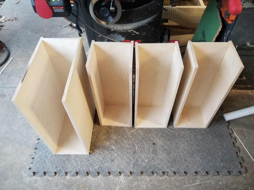
Meanwhile, as the foot board for the tub must wait until a few coats of varnish have come and gone, all the other tests are done, and the tub is as prepped as I can make it, I still had a fair bit of daylight left to spend on the weekend but no right-sized projects to advance. And then I thought of the tansu stair drawers! I could fabricate those.
After some measuring, some double-checking, some thinking, and a fair bit of time at the table saw, the four drawer bodies (less their fronts — or maybe their backs!) were done. Yes, one of them is double-deep. That’s just how the stairway went. What kind of things can go in such a drawer? I’m not sure, honestly, but we’ll think of something! Or partition it.
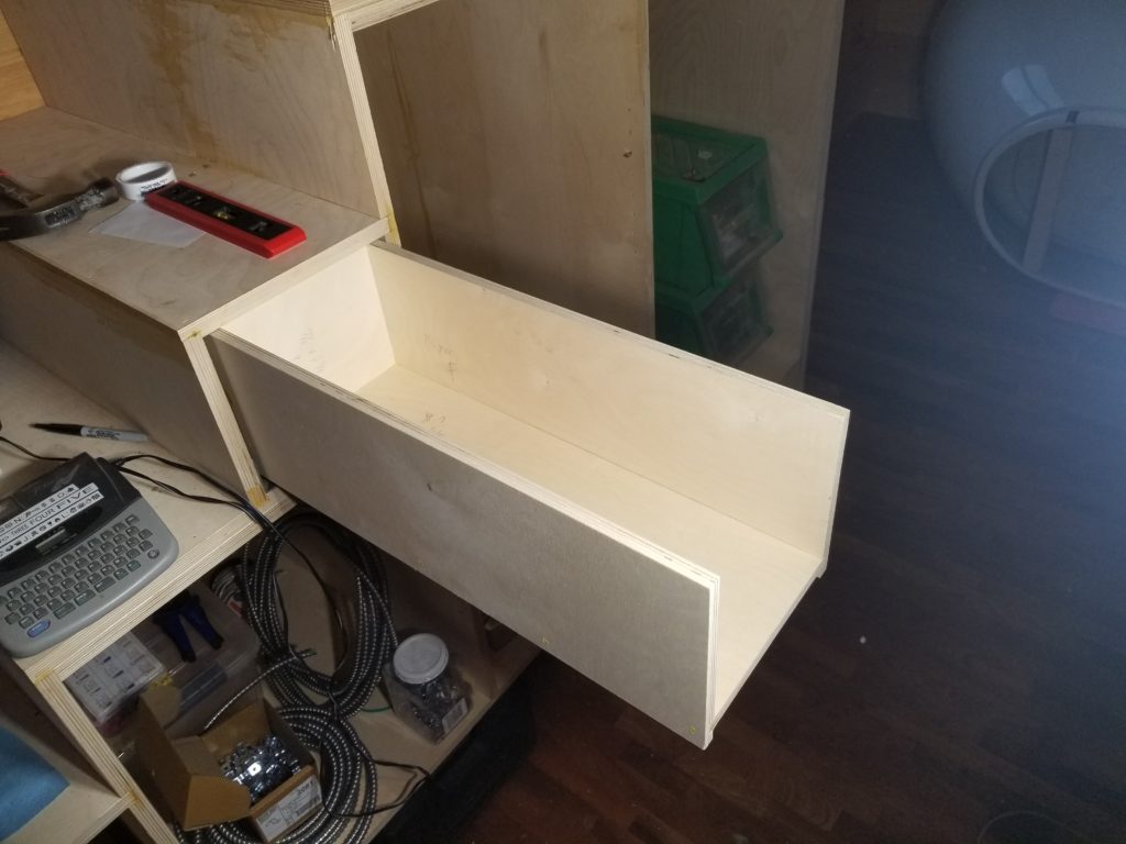
As a reminder, these drawers fit into nooks in the stairway to the Cozy Loft. Shown here, with lots of random construction stuff on the stairs and in the cabinet bays, one of the drawer bodies docked mostly into the stair housing.
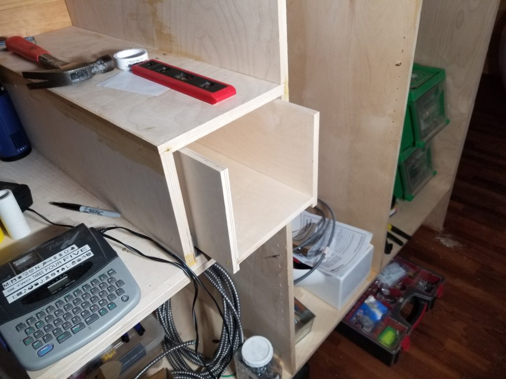
These are full extension under-mount drawer slides. This 21 inch drawer comes fully out.
The widgets that attach the drawer slides to the drawer boxes themselves (well, the drawers straddle the slides, so the attachment happens just at the front to latch them to the slides) are a bit mysterious and the “instructions” for the set consisted of exactly two diagrams showing some critical measurements for drawer box and slides but notably absent were these clearly vital widgets. I wrote to the vendor asking about them but got no response. I think I know how they are to be used, but I’m not convinced they will do a good job at their job they way they seem to be designed. When one drawer’s glue has dried, I’ll attach the widgets and see how it goes. If it turns out the widgets don’t work well, I have a plan B for securing the drawers to the slides, so I’m not especially worried about it. Still, it would have been nice for the slides to have come with more detailed instructions about how this system is supposed to go together.