My mission for this next phase was to get the power system fully commissioned. This included buying another 3 of those battery modules (for a total of four; approximately one day’s worth of household electrical operations can be stored per each), wiring it all up, setting all the settings on all the equipment, and generally proving the whole thing, minus the actual charging-by-solar, since I don’t have solar panels right now.
The batteries were expected to ship mostly discharged and anyway, I will want a way to charge them before I have the solar array installed (which won’t be done til the house is sited). A generator is an obvious option but they are noisy and frankly, what I really wanted to do was just “plug the house in” for the winter so I could keep a little electric heater in there to prevent freezing. Electric heat consumes energy like crazy – I’d be at it with the generator every day or two. Not exactly my idea of fun. However, I could just plug the house’s generator connection directly to grid power from the main house and let the batteries do their real job: being backup in the case of power loss (which also happens when we use the dryer, for reasons which will become clear later). So step 1 of that is to install a “generator” outlet to plug the house into.
Ultimately, what seemed most rational was to simply tap into the workshop subpanel which was close at hand, had an empty space for a new 2-pole breaker, and had the capacity, electrically speaking, to handle the load. The workshop subpanel, as it turns out, has an unusual arrangement with the main house. The subpanel itself plugs in (at the end of a conduit run between the garage and the house)… to the electric dryer outlet! Yep, the entire workshop has a (30 amp, 240V) power cord. There is only one dryer outlet, though, so either the dryer runs or the workshop runs. Why is this so? Well, I rent this house and didn’t want to make a major modification to the electrical system so I just ran new wire through the existing garage-to-basement conduit, which just so happened to come out near the dryer outlet, to power more stuff in the workshop than the previously-existing wire could handle. Presto, workshop subpanel… but only when the dryer isn’t in use. In practice, this is rarely an issue. Anyway, that’s why the workshop suffers “power loss” when we use the dryer: it gets unplugged!
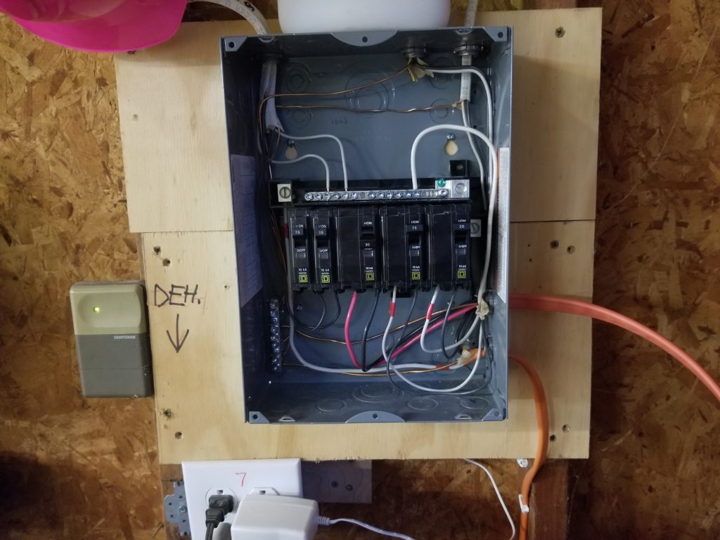
The workshop panel is pretty straight-forward. If it looks a lot like the load centers in the tiny house that’s because it’s the same model. I’ve used this model several times in different places and I’m pretty fond of it. It’s a Square D “QO” panel, if you’re curious. The orange cable entering from the bottom right is the other end of the dryer plug. The orange cord just above it is the new “generator” outlet for the house. Nothing too exciting to see here, but getting this going is intrinsically exciting, even if this particular part is unremarkable 🙂
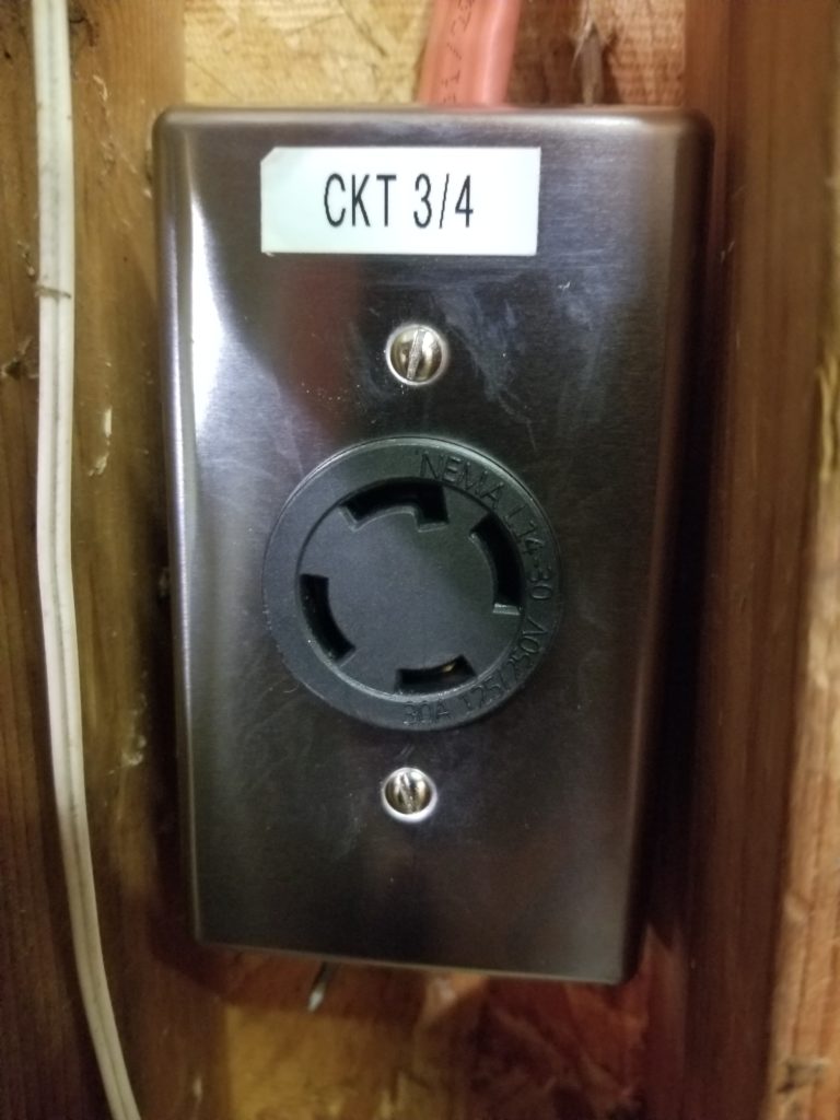
Behold, the outlet. This is a 30-amp, 240V twist-lock socket, which, if you have a generator, you probably also have on your generator.
You might notice that this outlet is in close quarters with the studs — there’s one on the right and another immediately on the left. That’s no problem for mounting the box, but…
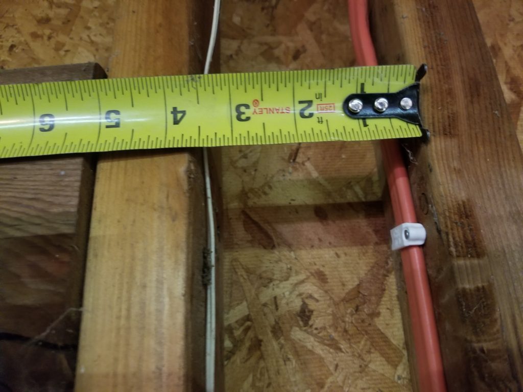
…one must secure the wires, even if there’s only 3.5″ of space. The question is, how on earth to hammer in those white staples? There’s no clearance to get at it from an angle. The only way is straight in.
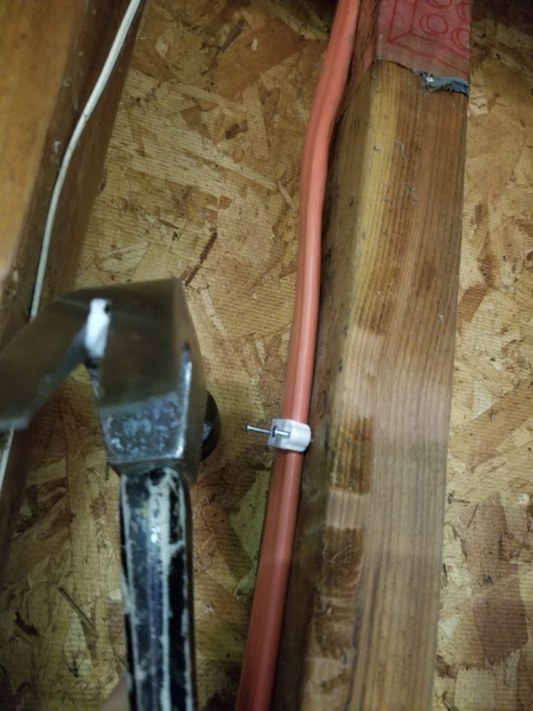
So straight in it went.
Did you know you can use a hammer laterally? You can. The head can totally take a beating from the side as well as on the heel, where it normally delivers impact. Of course, when there’s only 3.5″ inches of clearance and some of that is consumed by the bulk of the hammer itself, there’s precious little room to swing. . . . thus very low momentum . . .
Thus very low impact and thus very slow going. But go it did. I was glad there were just one or two such staples to install. It was no kind of fun.
Part of the power system is the 12VDC section that runs all the “RV” devices like the water pump, LED lights, and water heater, to name a few. Remember from a little bit ago that the circuit breaker I bought for that turned out to be the wrong voltage? Well, the vendor took responsibility for their error and refunded me the full amount, but I still had a problem to solve. I did find a suitable new breaker, properly rated for the voltages at hand, but it turns out I underestimated the depth of this standard metal junction box, into which I was planning to mount it.
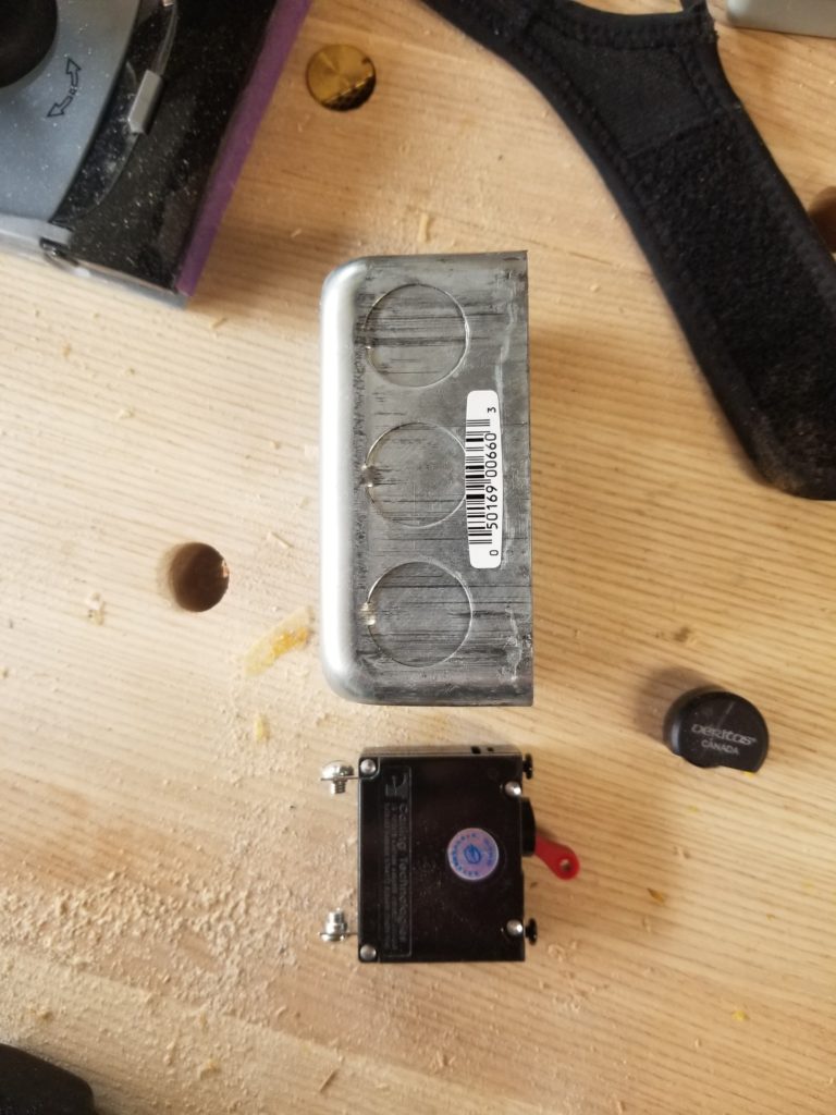
Oops. This caused me to scramble a bit in the workshop, looking for a bigger box, either wide enough to mount the breaker sideways or deep enough to mount it frontways. I couldn’t find anything that would work and browsing the home center’s inventory, there wasn’t anything right-sized. Then I had an idea: what I really need is some sheet metal. I don’t care if it’s a box. I just need to be able to mount the breaker to something secure. If I need it enclosed, I can certainly make a wooden cover. Back to the junk pile to see what I can find.

Well, I’ve got a couple of these octagonal junction box covers. They’re sheet metal. They’re really not the right configuration to be a stand-alone mount for the breaker, though.
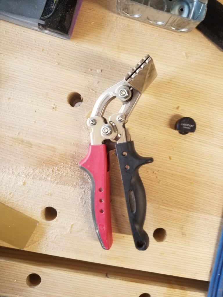
I’ve got one of these metal folding tools, which can bend it into a bracket – okay, good start. And a drill that can make mounting holes. Good, good. And a bigger metal-boring bit that can handle the nose of the breaker. Great! I can do this.
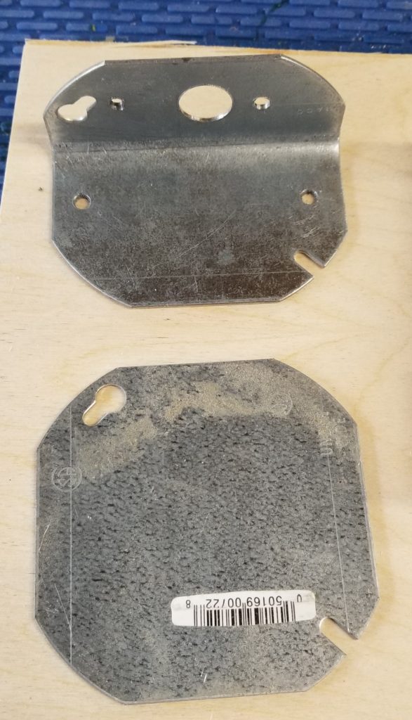
Ta-da! A mounting bracket for the breaker. Perfect. Well, it will be perfect once I file down that burr on the left. I don’t care about the slot and the keyhole left from the cover’s former life. They add “character”.
And so it was: the 12VDC power supply now has a breaker between it and the main battery bus (48V nominal). Now to mount it near the power center and wire it in.
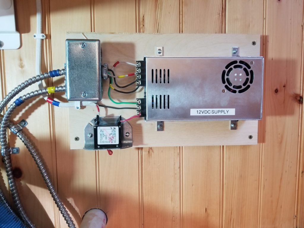
The armored cables coming out of the junction box take the 12VDC (at nearly 40 amps, which is why there are two AWG 12 cables in parallel) down to the DC load center. The white cable with the red and blue tape goes to the battery bus bars and ends here:
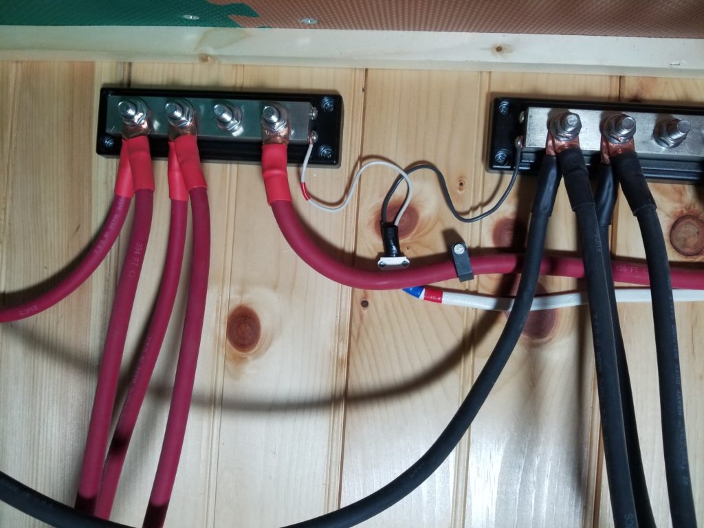
Compared with those monster cables that head off to the battery modules, this AWG 14 wire looks positively puny! But at 48V, even 15A nominal is over 700 Watts, more than the power supply will need, so this wire is fine. There will eventually be covers over all this, but until all the batteries are installed, the covers stay off in case I need to access the terminals.
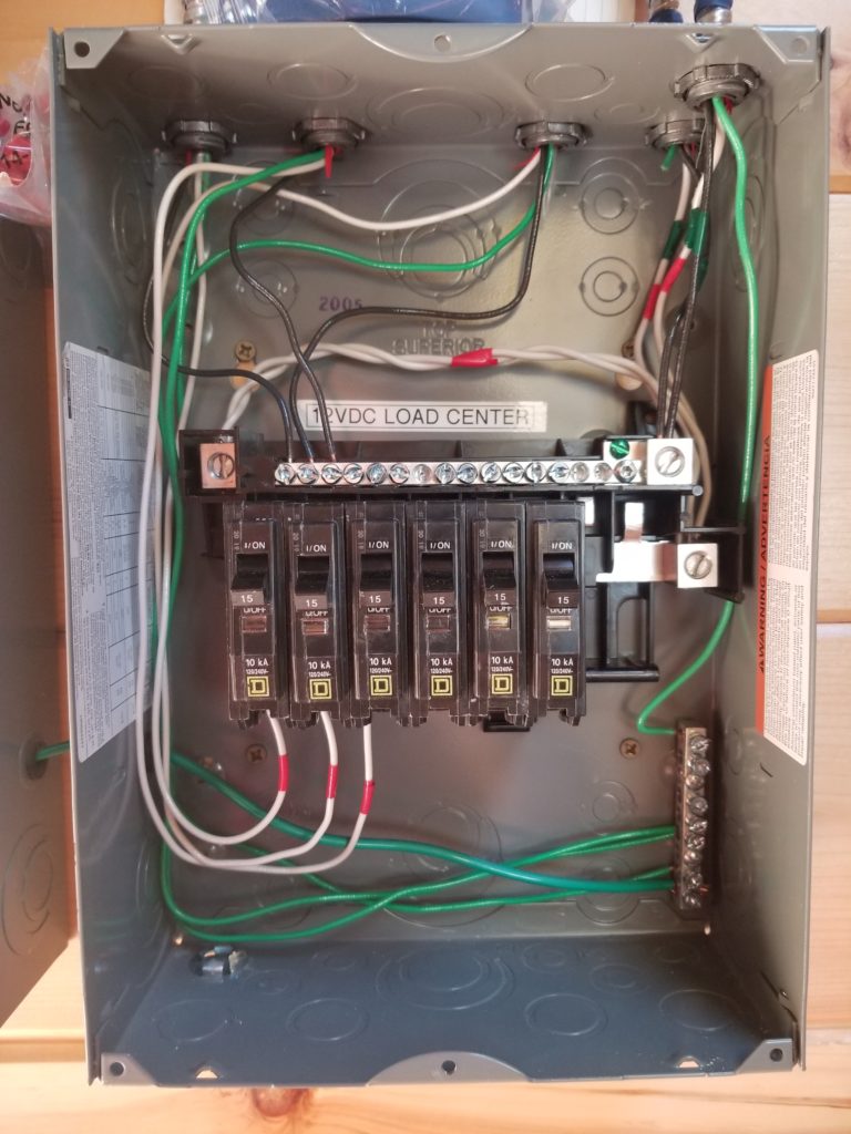
Down at the DC Load Center, things are taking shape. The temporary bus wire from before (there just to energize the panel to test the lights) have been replaced with a pair of AWG 12 wires (white twist; each good for 20A = pair good for 40A), more appropriate to the true maximum power rating of my 12V DC supply (480W @ 12V = 40A). In truth, I do not expect to be drawing even half that on a regular basis, but for safety’s sake, always size the wires to and in a panel consistent with the supply. So where is the pair of black wires for the other side? They enter the top bus on the right (green tape). The two cables from the power supply enter this box at the upper right. So far, so good, still decently tidy in the load center.
Okay! 12VDC system is all ready to go. Time to hook up the batteries, plug it all in, set all the settings, and make it go!
I got the three new battery modules a few days ago. As I unpacked them I noticed that two of them were slightly different than the third, which itself was just like the one I already had. Specifically, in addition to their built-in control and management systems, they each have a built-in circuit breaker. A big one, 80A. The two modules that were different, though, had 100A breakers. That’s a significant difference. These two modules also had sequential serial numbers. I wonder if there was a mistake at the factory. The module would probably pass all its tests with a too-big breaker, so I’m not surprised it got through quality control by the numbers, but I am surprised nobody noticed the “100” where an “80” should be, right there on the switch that somebody’s finger had to push to turn the modules off prior to packing in their shipping cartons.
Because this is a safety device and because the 100 is more permissive (therefore quite possibly less safe) than the 80, I have decided not to commission the battery system until I have made contact with the manufacturer and discussed this. I called on Saturday but didn’t get through to anyone. I left a message in their inbox about it, though, and will follow up on Monday with another phone call to try to resolve this quickly.
I suppose I could bring up the other parts of the power system without the batteries, but I’d rather do it as a complete system, so I’ll wait.
For now, though, no power system bring-up which also means no water system test, either. If I were especially eager or desperate, I could rig up something to make it happen, but I’d rather do it the way I mean to do it and if that requires me to wait a few days to resolve a thing, so be it. If the battery modules need to be returned, though, that will be a big inconvenience no matter how it happens, since the vendor is a 90 minute drive away and I really don’t enjoy moving these heavy things up and down a ladder (they’re all in the loft right now).
Awrighty then, power system on hold, time to work on some other things.
One remaining task is the gray water lift line up to the SUL. I was waiting til the other three things that pass through that corner of the ceiling of the T.H.R.O.N.E. Room had been properly sealed in their clearance holes because once running the gray water line, there was going to be no getting back there. Well, they’re done, so time to do this one. And so it was:

The GW line is the one with the white fitting on top of the lift pump body. The reason for the 45 degree angle rather than a 90 elbow is simply that it’s easier for the pump to turn two half-corners than one full corner. that’s the same reason the fresh water riser (seen more or less center, just above the hot & cold supply lines) also has a pair of 45s where it turns.
I realized, though, that the GW lift line will need some support. I’m not quite sure how to do that, given there’s no easy way to install some kind of blocking, like I did for the other pipes. For now, it’s a bungee cord (red) to the dump valve bracket, but obviously that’s not a long-term solution. That said, the bracket is actually in a prime location to do the necessary work, so maybe some kind of strap here is indeed the answer. Looking at the picture just now, I become a little concerned that the generous diagonal of that pipe might interfere with the tub. It’s hard to say.
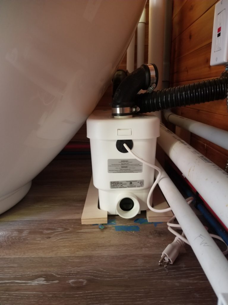
This is the only picture of the tub/lift pump fit I’ve got. The new line starts close to the top of the pump body, toward the right side, and has a diagonal run to the corner where the pipes go vertical, so maybe it clears, given the curvature of the tub in three dimensions? I guess there’s only one way to find out… and that way will wait until I test-fit the tub with the runners. I’ll just have to be mindful of this pipe when I do that.
If it turns out to interfere, I can cut the angle out and make a more corner-like transition there instead. It’ll be more work for the pump, but not a lot. The angle I built was just to go easy on it because I could. Maybe I can’t? We’ll find out later!
In the picture with the red bungee, you can also see a section of that fancy chemical-resistant 1.5″ clear tubing now fit to the bottom of the gray water lift pump (fitting is the white thing at the far right of the photo below). Now I can show you what I meant when I said I was going to just use a hump to make an inline trap.
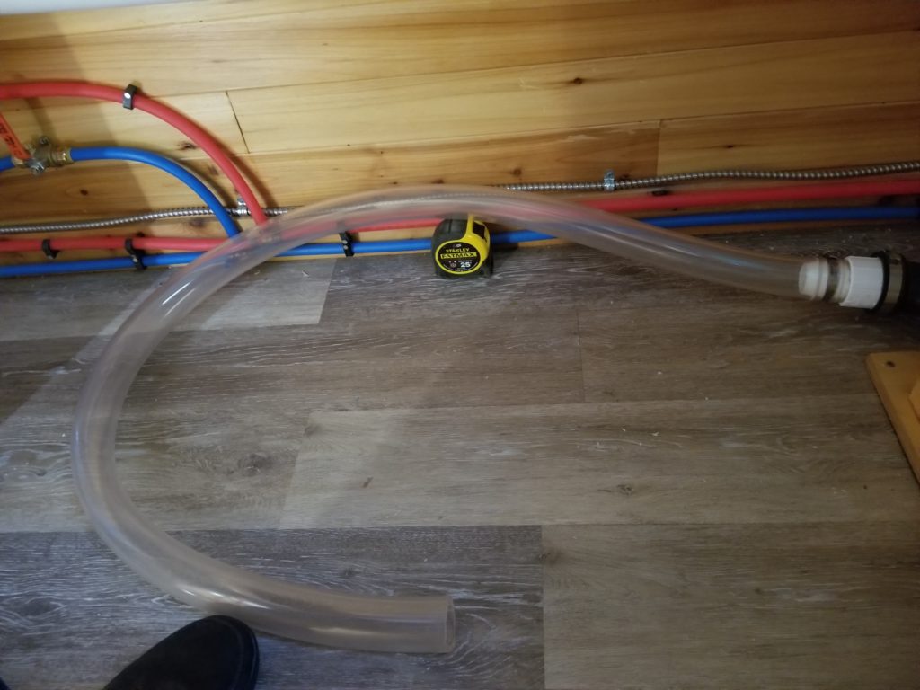
Imagine that the open end of the tubing is instead connected to the tub drain. The floor of the tub is actually 5″ from its footing. That means to drain the tub, the drain line itself simply has to be lower than 5″ (plus the thickness of the tub floor, if we’re going to be technical) in order for all the water to leave the tub. In this scene, the tape measure is roughly 3″ tall and the tubing is 1.5″ inside diameter, putting even the highest inside point of of the tubing at 4.5″ from the floor, still below the tub drain’s lowest point, so all the water in the tub — being higher than this — can easily cause flow over the hump. When the tub nears empty, the water level is still higher than the hump, but here’s where it gets interesting. The last little bit of water to leave the tub will fill the tubing (tub-ing?) and displace the water ahead of it into the lift pump, but without water behind it that’s got some altitude (when in the tub, water is at least 5″ from the floor level), nothing will push that final slug over that 3″ hump. Instead, that water will just stay there, below the floor of the tub, occupying the segment between the drain and the hump. That is actually exactly what I want. This slug of water becomes equivalent to a P-trap, isolating the drain from any foul air in the gray water lift pump body.
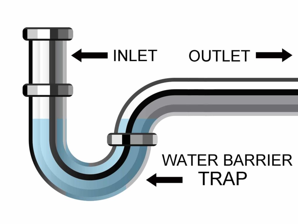
Instead of having a U-shaped fitting below the tub, I raise the outflow tube a little, creating an equivalent loop of tubing to form the barrier as shown in this illustration.
I’m not quite ready to work on the tub install just yet — I really want to get the power system done and all the water lines pressure tested first — so with the remaining work time this weekend, I installed the side car covers for the T.H.R.O.N.E bench itself. In an attempt to maximize the volume and accessibility of those side cars, I had cut the openings quite large (like a year ago!). This is good for getting things in and out, but also means there’s precious little margin for things like hinges! Even a piano hinge was too wide for that narrow strip of deck between the edge of the cut-out and the wall! Okay, then, how about some fancy spring-loaded, non-mortise hinges than can do a full-inset door? Yes, that will look nice and solves the problem of holding the doors open (and closed). The thing is… I didn’t mark for the hinges before things got crowded in there, so now I have to mark the hinges on the doors, then transfer those lines to the opening. This is considerably more trouble than you might think at first because of how cramped everything is and the inconvenient truth that the thickness of the door means I can’t just lay a simple straight edge to transfer the line — the ruler would stand off the plane of where I wanted to mark! Fortunately, I have a very thin metal ruler which is flexible, so I could hold it against the mark on the door and bend it so it was flush to where I wanted to transfer the mark. I extended the mark on the door several inches so I had a line for reference, not just a mark, in hopes of keeping the straight edge… straight. I got pretty close, though honestly the final results were not as well-fitting as I am capable of, had I more working room and applied more forethought. Simply measuring for the hinges, rather than transferring marks, would have been worse, I promise. The angles involved were such that there was approximately no chance that I could accurately read a ruler or make a freehand mark somewhere I meant to. Instead, really, the only hope was to align a flexible straight edge with the line on the door, which was propped up in place, and transfer the line with a 0.5mm pencil. No pictures of that – it took all three of my hands just to do it. No hands left over for picture-taking.
Then came the next problem: pilot holes for the screws. No way was my drill fitting in this space! Shit. Okay… I know better than to think I can drive a #6 screw into 2x material from the side and expect it to go in reasonably straight or even get started without a great deal of fuss. Then I had an idea.. I can’t get a drill in here, but I can at least make a starting divot that will help the screw get some traction and provide at least a little bit of a “pilot hole”, shallow though it may be.
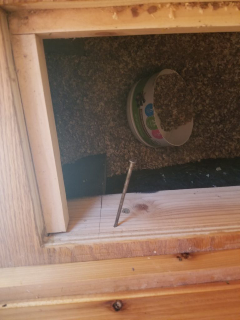
Conveniently, this hole was so shallow it didn’t have to be straight, either, which is a good thing since for the same reason I couldn’t get a drill (or a real screw driver) in there, I also couldn’t get my hammer perpendicular to the hole I wanted. An off-angle strike I could do, though, and that gave me a starting divot for the screws and it was almost enough. I made it work.
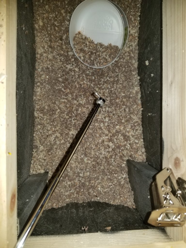
So no legit screwdriver would fit in here, either and even if it did, turning it, perpendicular to the axis of entry, was going to be a huge bother with a conventional screwdriver. My little ratchet tool once again to the rescue! Ironically, I had to use an extender bit with the close-proximity tool to get the right combination of drive-from-the-side, small turning angles, and clearance over the hinge body itself. This reminds me a bit of driving those lag screws for the fresh water tank’s hold-down brackets, but on a much, much smaller scale.
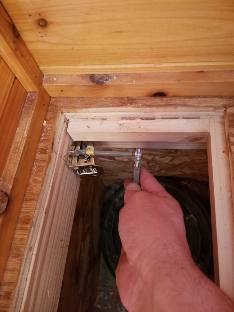
While the angle distorts the relative size of my hand a bit, you can see what I mean about this being close quarters! It turned out that my impact driver, with a medium bit, could actually reach most of these screws, so once I got them started, I could drive many of them home with ease rather than with ratchet tool.
Sometimes, though, the little screw would drop into the side car before it got purchase on the wood. That wasn’t a problem really for this bay shown, but the other one happened to be half full of sawdust. A perfect haystack for my screw-needle to fall into and disappear. Gone are the days that manufacturers give you a few extra screws, so I really needed to get this one back.
Good thing I have a magnet on a stick! I just had to fish around in there for a little while til I heard a tiny tink and there it was! This actually happened several times, but I was able to recover the screw each time, occasionally with considerably fishing, sometimes I got lucky and found it quickly.
Naturally, I wished there were a way to hold the screw securely as I maneuvered it and the driver and the hinge into place. Then I had an idea! I can use my magnet-on-a-stick and ignore the stick part!

The bit itself was sufficiently ferrous that the magnetism carried through it and gently held the screw to the tip of the bit. It wasn’t a great hold, but it was enough to stop fumbling the screw into the sawdust until I could get it pushed into the divot and give it a half turn to engage it just enough to hold it in place.
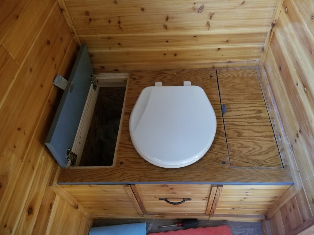
And there it is, my not-so-great-fitting inset door, shown here with a tab of duct tape as a temporary pull. The one on the left has an even bigger, less-even gap than the one I am willing to show you. I’m not proud of it, but I don’t think there was a way to do it better, given all the constraints. In retrospect, if instead of attempting to attach the hinges to the frame of the opening and then to the door I did this like a pre-hung entry door, I probably could have gotten much better results and it would have gone much more quickly than all this cramped-space work. I didn’t think of that til 3 hours after I finished, though (that would be now). Ah, well. It would have involved destroying the rim I’d installed to hold the door flush when closed anyway. I’m pretty sure it’s glued in place. If it is, then such a revision is a non-starter. Anyway, it’s done now and though imperfect, it will do the job. This whole project — the whole project — has a major aspect of acceptance and imperfection running through it. These two cabinet doors have a lot of company.
What will I use for door pulls? I don’t know yet. When open, there’s really only like 3/4″ between the face of the doors and the wall, so at that dimension, pretty much nothing will do. The hinges will reliably hold the doors open if they’re stood off the wall a bit, so maybe there’s clearance for a big-enough pull of some kind. If not, I can always do a rope loop or knot and let the loop flop down when the door is open, yet have enough length to the loop that my big paws can get in there to open it. We shall see. That’s a little project for another day.
I hope to talk to tech support about the circuit breakers on the battery modules early next week and come up with a plan from there. I’m keen to get the power system up and running ASAP.