…which is not quite as good as hot and cold running water, but it’s a start!
Strangely, before I can install the tub, I need to get the power system mostly online. Why? Because I need to test the water lines that run behind the tub before installing the tub. The electric is for the water pump. The water pump is actually on the 12V DC system, which runs off the 48V battery bank (obviously with something in between to make 12 from 48). I just got my refund for the race car batteries I decided to return, so now I can afford the rest of the batteries I did decide to use, which is the next step in getting the power system ready. Actually, I should be able to bring up the power system shortly after all the batteries are installed. I’ll need to hook up either a generator or wire a 240V-30A outlet to plug it into to charge it up in lieu of an actual solar array (no sense buying that til I have a place to set it up — prices keep coming down and efficiency keeps going up; waiting makes a lot of sense). I have placed the order for the batteries and expect to have them later this week.
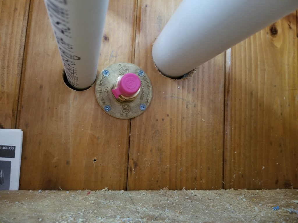
What else needs to get done? The propane line needs to run from the Propane Porch (that’s why I call it that) through the T.H.R.O.N.E. Room, up to the loft… after the lights, which are now installed, so in it goes. I chose corrugated stainless steel tubing as an easy way to run the line — it’s flexible so I can do a single continuous run from the porch up to the loft, taking a few turns along the way. Here’s the terminus in the porch proper, waiting for me to install the regulator and then connect that to this. The hole I’m using for the propane line was previously drilled for a different purpose (one that didn’t feature a big brass flange) — I got lucky. It just barely fits. Getting a screw driver and a hand in there was special fun. That tiny ratchet driver to the rescue, again.
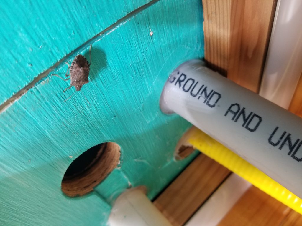
You can see it going up into the loft (yellow ribbed hose passing through the mural) and being carefully inspected by a local stink bug. While I’m here, it’s time to seal up those holes, before I run the last pipe through that last hole, because once I put something there, no way can I get to the other pipes/conduit to seal them. The white and gray pipes are sealed here. The propane line is partially sealed – the hole it passes through (originally for something bigger) was too big to seal all in one shot, so I’m doing it in parts. When it’s done, I can install (and seal) that last pipe, which is the graywater lift pipe.
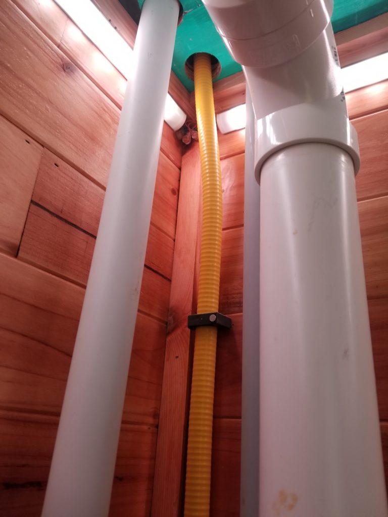
See those tiny connectors in the corner, between the lights, behind the propane line?
Yeah, now you can really appreciate why they had to go in first. With that semi-rigid yellow pipe in place, there’s no getting into that corner unless one is a spider (I’m not a spider).
The next thing on the list is the water heater. If I want to have cold and cold standing water, I am going to need all my plumbing plumbed and that includes the water heater. While surveying the exterior of the house to in preparation for putting up the ladder (the heater’s vent will be way up high and require some exterior work), I noticed the house had listed a bit to the left. This is not particularly surprising, it weighs several thousand pounds and has been in one place for years. The driveway has shifted a little, under the weight. Out comes the bottle jack. This little thing cost me less than $50 and somehow manages to be strong enough to lift this whole house. Amazing.
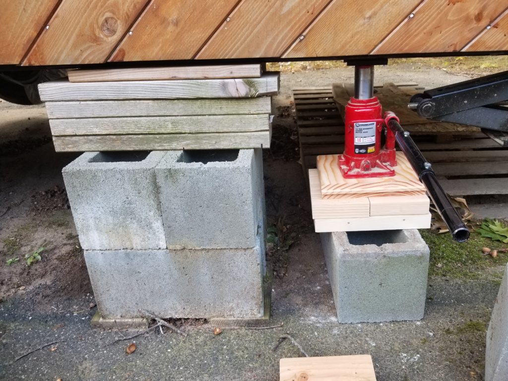
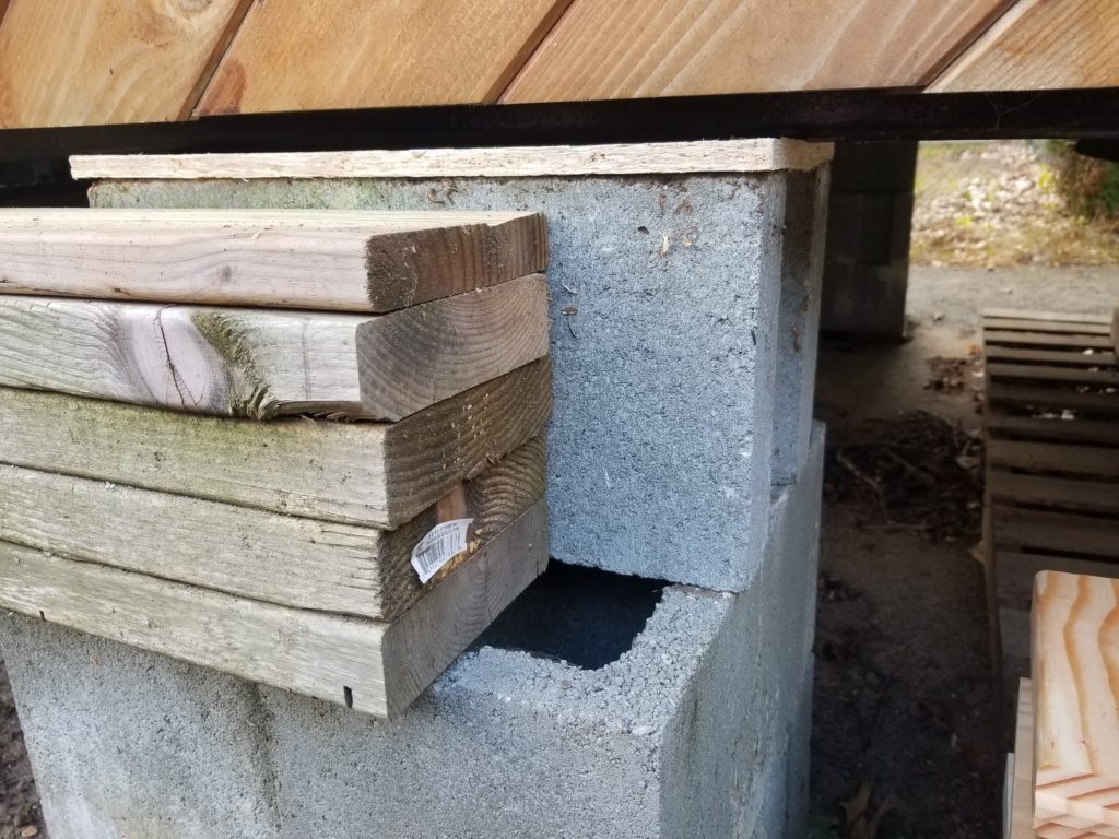
How much higher did it have to go? About 1.5 inches, give or take. Enough that I could swap out this stack of 2x stock for another cinder block.
All nice and level again.
Back to the water heater. No, before I install the water heater, I need to install the pressure pump and accumulator, which sit next to it, but before them, I’d better take care of strapping in the fresh water tank, before things get even more crowded up there.
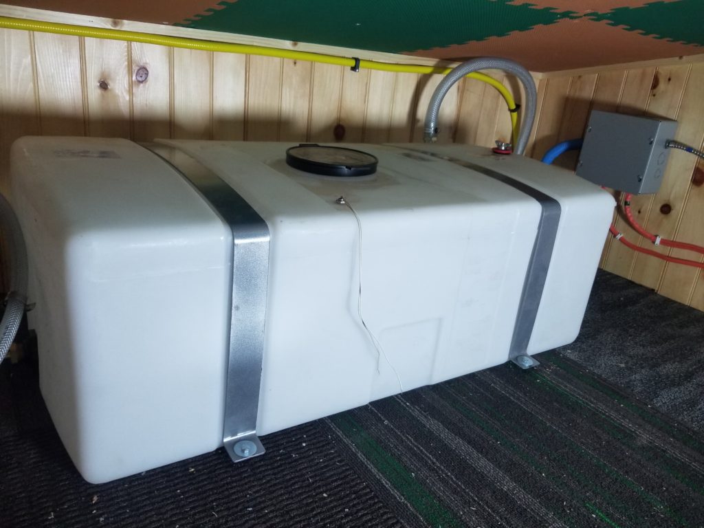
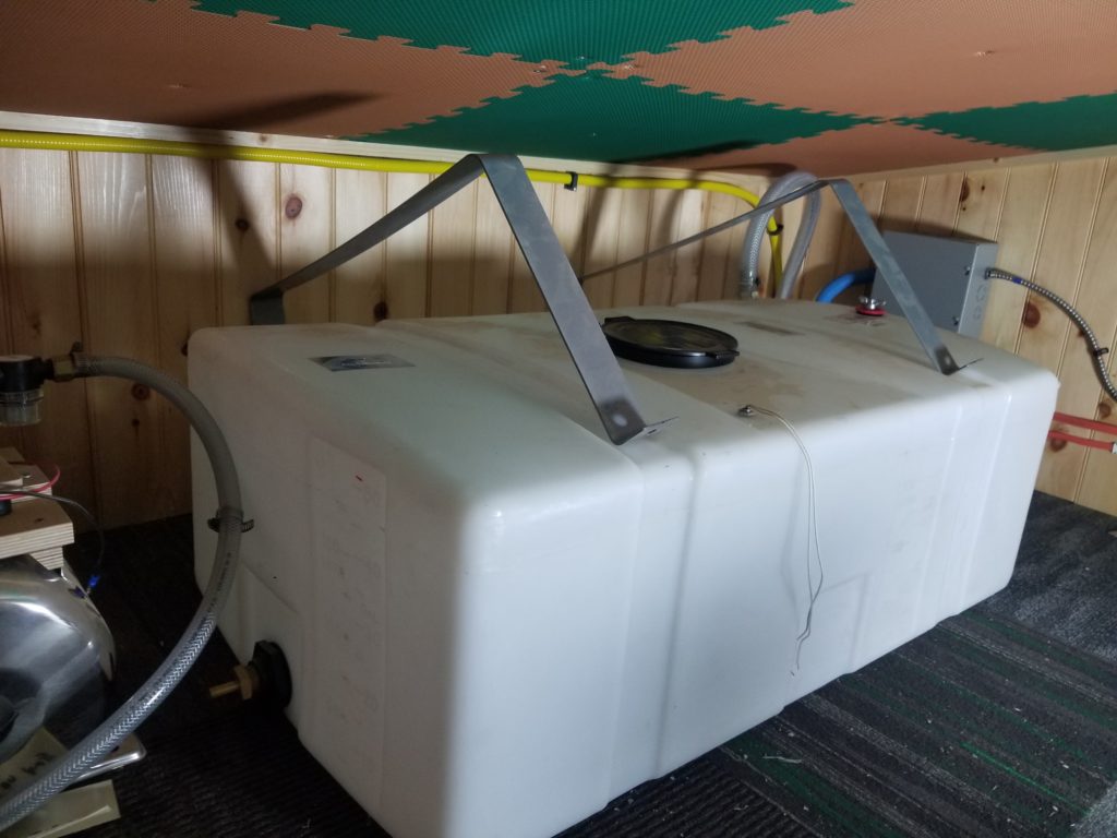
Here’s the fresh water tank, all tucked in. You can see the propane line (yellow) as it comes up through the floor (ceiling) and heads on over to the water heater. The big translucent hose is the filler for the tank. You’ll notice the straps for the tank have tiny feet with lag bolts to the floor. It wasn’t too much trouble to drive those in (remember: there’s a gray water tank built into the floor, so I’ve got to be very careful about the lengths of screws driven into the floor!). However, there’s less than 1.5 inches of clearance behind the tank, between it and the wall. How, exactly, is one to drive those bolts??
First, I just placed the straps without the tank.
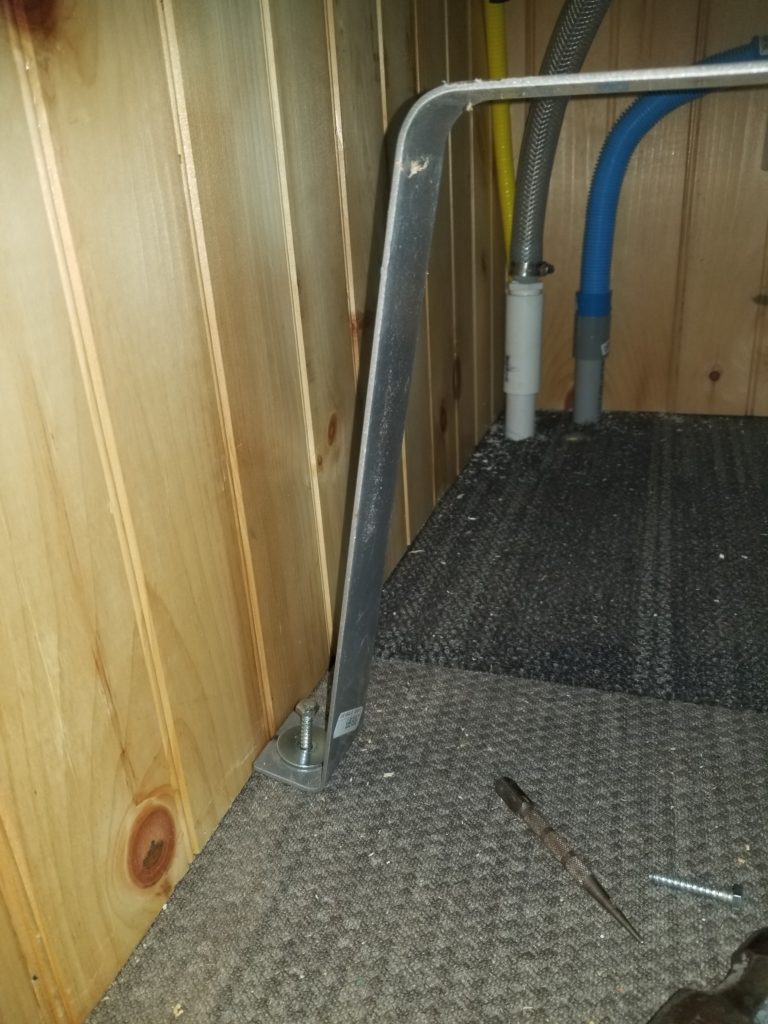
A ratchet tool could probably make headway driving that bolt, but it would be really tedious doing this 1/8 turn at a time. Also, if I drive the bolt all the way in, the strap will be relatively tight to the floor and then I won’t be able to install the tank under it! So I need to drive this bolt in just enough to have staying power, then install the tank, then drive it home with the tank in place. No way I’m getting any close-work tool in there once the tank is in front of it.
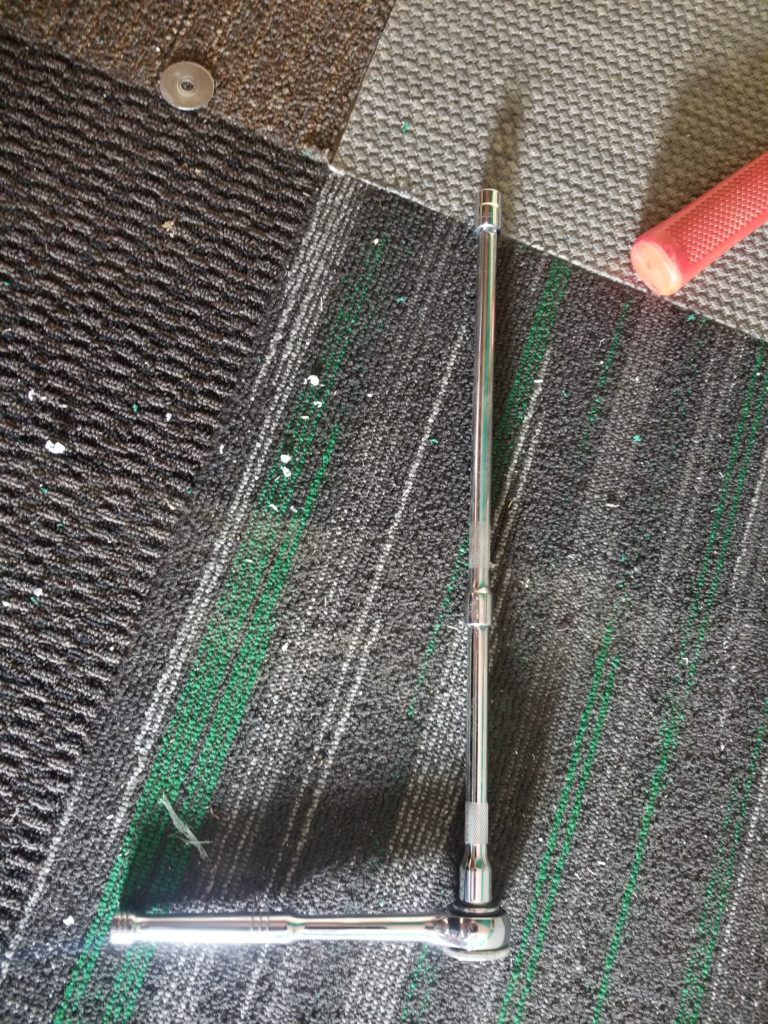
Fortunately, I am prepared! If I stack two extenders together, I have a socket tool that is long enough to reach the bolt head from above the straps. There, I can have full swing of the ratchet tool and get it done. I will need a mirror to land the socket on the bolt head, but I’ve got one of those, too.
Bolts in, just enough, now spring the straps back a little and slide the tank in place. It looks a little mantis-like here, doesn’t it?
And so it was done. I wound up using the extended ratchet tool for the front bolts, too, simply because it let me have full swing of the tool rather than being in such close quarters with the tank. It was done in short work. You can bet I was very very careful when I pre-drilled the holes in the floor not to go into the graywater tank below! Did I succeed in missing it? Well, I sure think so. I should have been able to feel the resistance on the drill change, too, which I didn’t, so I think everything’s okay. I won’t know til it doesn’t leak… and if it does leak, I might not notice, either, since a small leak won’t show, now that the ceiling is all sealed up. Either it’s okay or it’s not. If not, eventually I’ll find out. I’m pretty sure it’s fine, though.
It turns out that extension was useful for screwing down the pressure pump/accumulator assembly, too, for similar reasons.
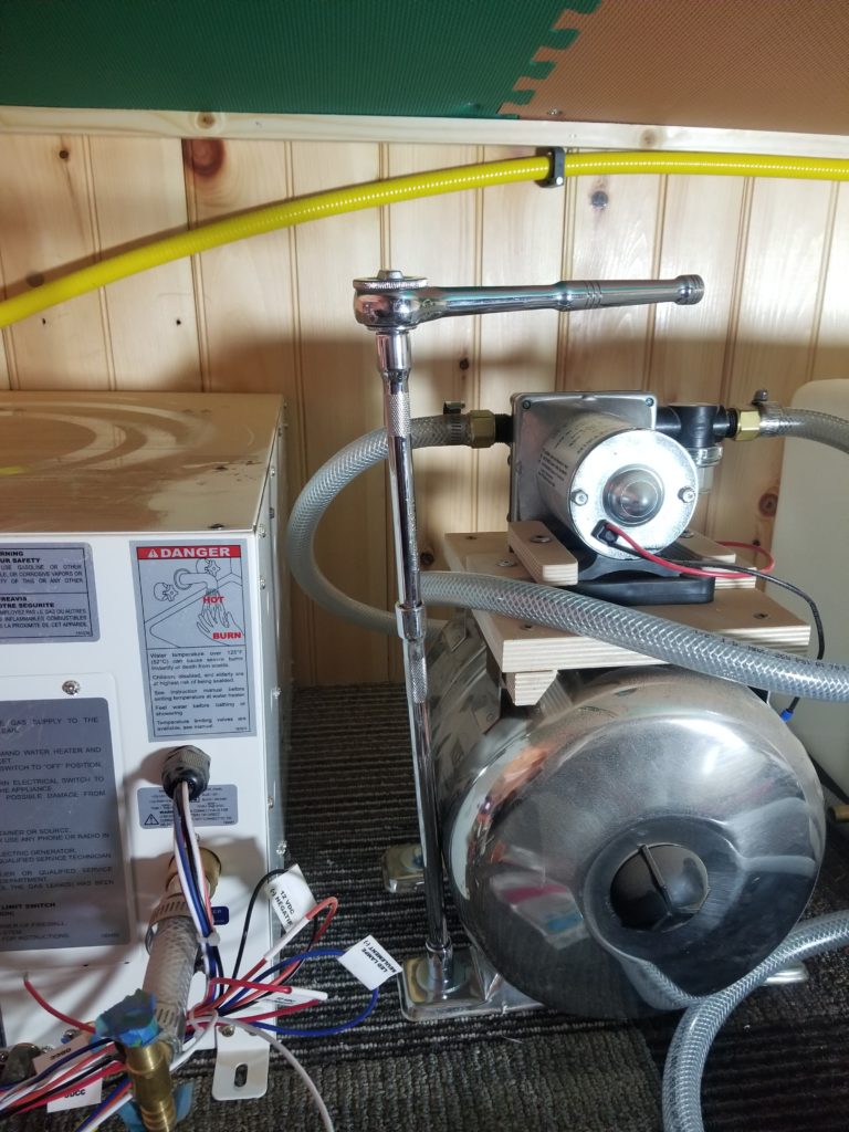
That’s the water heater on the left, and its turn is next! The only really critical bit of installation for that is getting the vent hole in the right place. It needs to be 9.5″ from the mounting deck and some distance from the right side. I don’t really care precisely where the right side is, I can have the water heater meet the vent on the left/right axis, but I really do need to get the height right. Measure three times. Get out the hole saw.
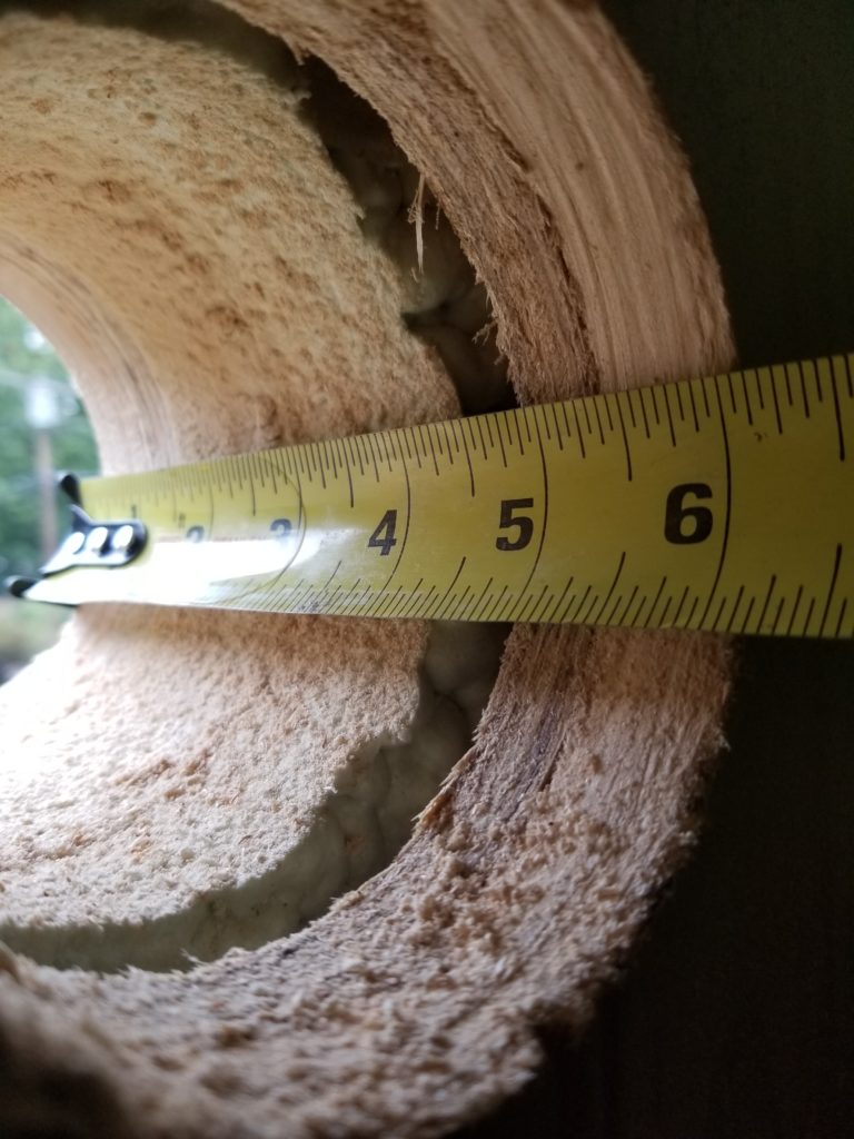
It was a pretty deep hole. I knew it would be – when shopping for the water heater, which is really designed for RVs (which have thin fiberglass shells, possibly with an inch or two of insulation), I had to also purchase the right-sized vent assembly. The very longest one they made accommodates a wall thickness of just over 6 inches. So I did some math. 3/4″ cedar siding. 7/16″ sheathing. 3.5″ suds. 7/16 inside sheathing. 3/4″ wainscoting. Where does that leave me, thickness wise? 5-7/8″ if it all fits together tight and is dimensionally accurate. I don’t actually know if the cedar is really 0.750 thick, ditto on the wainscoting. It is whatever it is. So what was it? It was a solid 6 inches is what it was. It looks to be 1/16 thicker because of the parallax here, but when viewed head-on, it’s 6. Whew. Just fits.
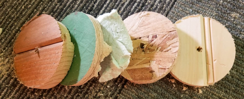
It was fun to see all the different layers of the wall system in the core, too.
Of course, this 6″ deep bore through the wall would be a bit of a challenge for any reasonable hole saw, like the 2″ deep one I have. Sure, you can bore for a while, clean out the plug, then keep going, but after a couple of those, you run out of available depth. Another extender to the rescue!
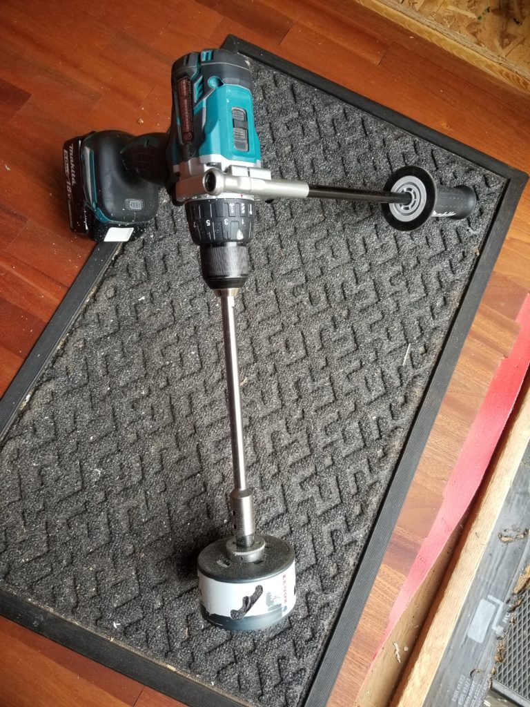
The perpendicular handle helps control the kick-back of the 3.75″ saw, which occasionally digs in and transmits the full power of this mighty drill back to my wrist if I didn’t have that outrigger to stabilize it. By the way, if you’re looking for a fantastic cordless drill, buy the brushless Makita 18V. It packs a ton of power and is very sturdy… just like every Makita tool I have ever used.
The hole saw had a nifty feature I’d never seen before — see that stair-step slot in the side? It’s designed to provide a fulcrum for an inserted screw driver so you can pry out the plug. The stair-step design lets you get behind the plug when it’s deep, then pry it out one step at a time. This worked great. I highly recommend this style (this one was by Lenox).
Hole drilled. Time to check the alignment with the heater body. It’s not absolutely perfect, but it is definitely (probably?) good enough. Seal it and screw it to the wall.
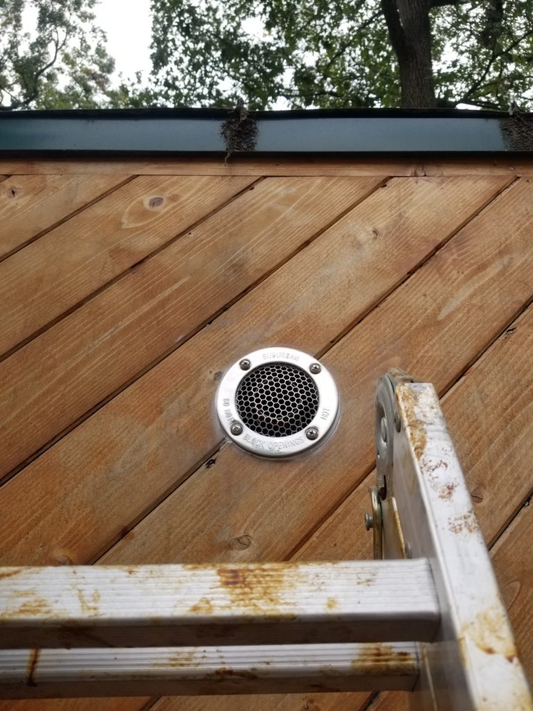
And so it was done. I was smart enough to squeeze a bunch of sealant onto the flange before climbing the ladder, so I didn’t have to fuss with the tube of silicone at height. It turns out I didn’t put quite enough on there, though, so I had to go back and squeeze on some at ladder-top anyway. Still, the vent at that point was in place and secure, so it wasn’t a lot of fussing.
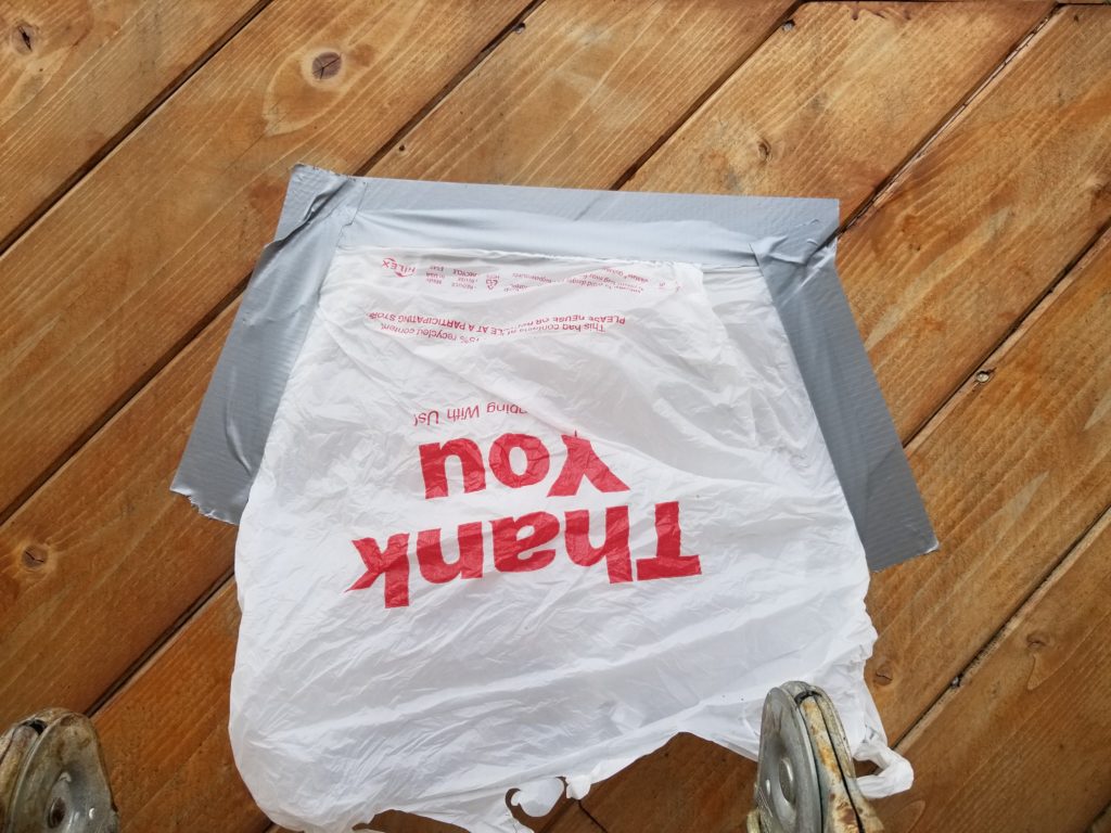
It was a little misty out while I was working, so in case it rained for real before the silicone had a chance to set, I put on this little rain bonnet fashioned from a plastic bag and some duct tape.
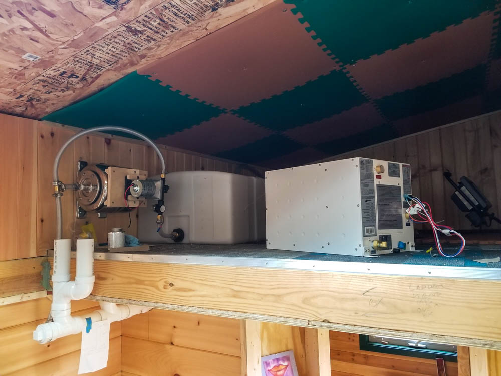
Vent in place, fresh water tank secure, pressure pump and accumulator secure, time to hook up the water lines to the water heater.
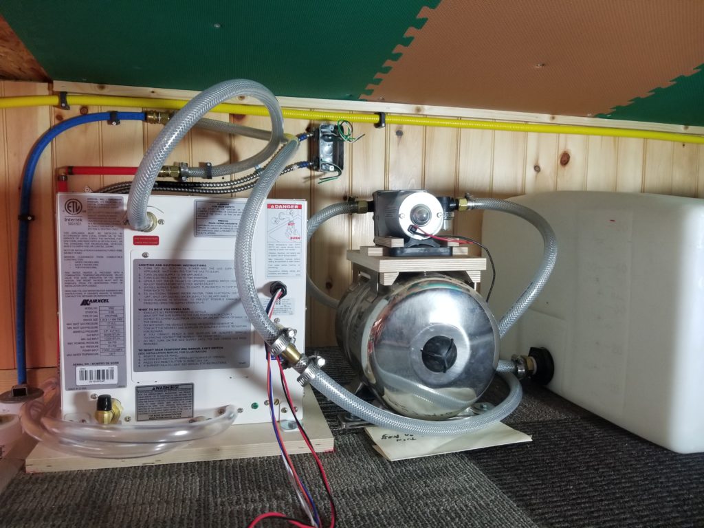
Shown here, all the hosiery! The longer-than-strictly-necessary lines to and from the pressure pump (sitting on top of the silver tank) are per recommendation of the pump manufacturer to help reduce transmission of pump vibrations to the building. That’s also why I’ve used flexible pressure hose here instead of nearly-rigid PEX, which I’ve used everywhere else.
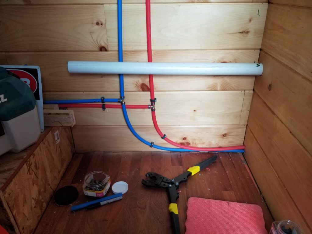
You can see the hot and cold feeds on the far left, as they go down to the first level for distribution to the kitchen and T.H.R.O.N.E. Room. The astute observer will notice the blue PEX is bent while the red line has a corner fitting. Why? The blue curve is the very tightest safe curve for the PEX. Bending the red in place to follow would simply be too tight. Elbow fitting it is, then. If I had really planned this out (I didn’t), I might have spaced the hot and cold risers differently so I could bend them both, but I wanted them where they are and started the run from below rather than above, so I didn’t realize there was going to be a tight turn til I got here. Maybe if I had started here instead of there, I would have run the lines so they could both have gentle bends, but that’s not how it happened and I have no motivation to undo the rest of it just to save an elbow. This system is small enough that one more corner isn’t going to meaningfully impact performance.
I have run the DC electric lines for the pump and the water heater to the junction box (center, top) but haven’t hooked them in yet. I need to use some other wire I don’t have on hand and crimp on matching connectors as appropriate. That’s a job for another day.
I did run the DC lines back to the load center, though, which is looking all the more legit as it accumulates circuits.
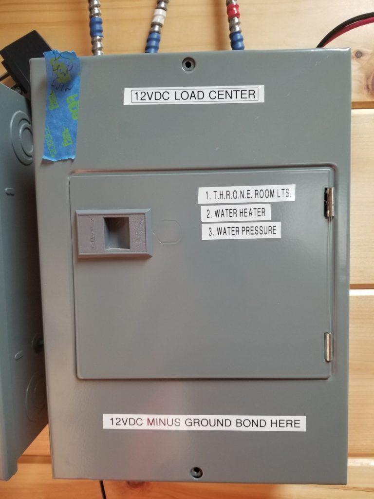
I put blue shrink sleeves on both ends of every low-voltage DC cable to help identify it as a low-voltage DC cable, since I’m actually using the same kind of cables for both AC and DC lines. Of course, I will never put both kinds of lines in the same junction box; that’s just asking for trouble.
Hey, speaking of DC Load Center, I was thinking about the 12V power supply — the one that runs off the 48V DC battery bank — and took a quick look at the circuit breaker I was planning to use for the main feed to the supply. I noticed something that gave me pause.
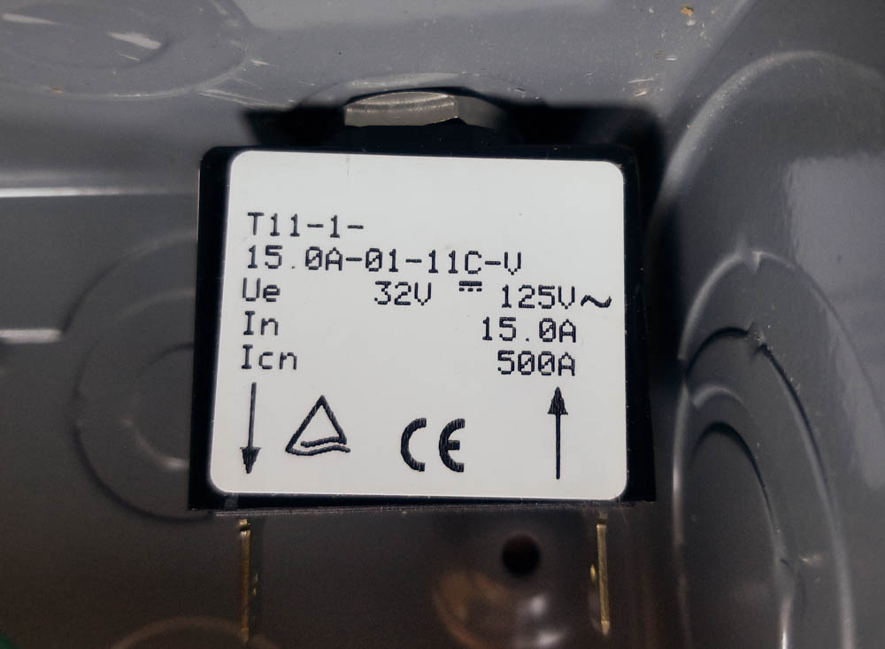
What’s wrong with this picture?
Nothing, it’s a perfectly fine picture, though maybe I cropped the bottom a little too close for a nice composition. The sticker on the breaker, on the other hand, shows that its DC rating is for 32V. That’s a real problem since I was planning to connect it to a 48V battery bank (which can be as high as 53 or so while charging). No bueno! I double checked the supplier’s web site and indeed, they (erroneously) have it listed as a 65V part. Nope. I wrote them a note and they admitted the error (after which I asked for authorization to return the part… it only cost me $12, so it’s not worth a ton of my effort, but it was their error, so they should take some responsibility here). Meanwhile, a new breaker (at the proper voltage rating) is en route.
Before we leave the SUL, I’d like to talk about the dual drains on the water heater. Behold:
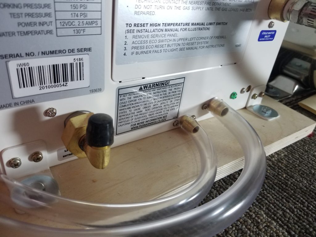
One (slightly higher, slightly larger) is for draining the heat exchanger coil for service/winterizing (if not using antifreeze). The other (slightly lower, slightly smaller) is for condensate. I’m guessing that one also gets any rain water that comes in through the vent, too. I found it annoying that they used 1/2″ ID tubing for one and 3/8″ ID tubing for the other, but what really got me was why did they need two drain ports? Why not just have one shared one? Maybe I’ll just tee them together and that’s that. Then it occurred to me why it is how it is and why I should definitely not tee them together here. The condensate drain is probably connected to a shallow pan below the combustion chamber. The heat exchanger coil is going to have a fair bit of water in it. Open that drain into (or teed with) the condensate pan and there’s gonna be a flood. Got it. Two drains. Check. Actually, I can tee them together, but only somewhat below this altitude such that there’s no chance of the drain flow going back up to the condensate pan. I have an idea about that, too, because there are two more little drain tubes I need to accommodate from up here, as well.
You may remember those two riser pipes at the end of the gray water storage tank. You can see them here, in this picture from a while ago, when I thought the pressure pump was going to go on the wall, before I realized I wanted to put the water heater there instead.
What were they for? They’re for level sensors for the gray water tank. One is a depth gauge, for reporting relative fullness, and the other is just a float switch that I originally intended to use as an interlock for the lift pump so it would stop lifting if the tank got full. I may still do that, but I rigged the gray water tank to have an emergency drain if it got over-full, so maybe I don’t care about that float switch now. Anyway, I do need to finish this, though, whatever it is I choose to do with them.
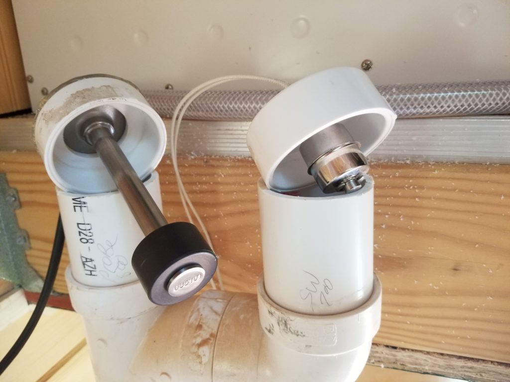
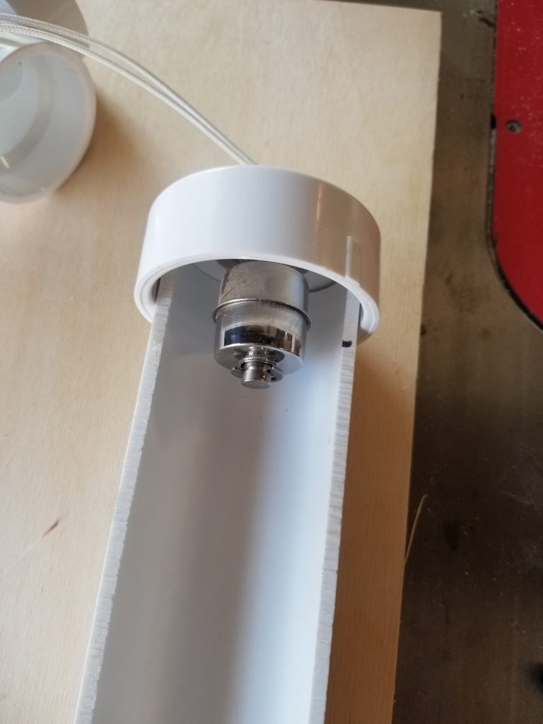
Here are the two sensors, the level sensor on the left (it is also a float; it has a magnet inside that communicates with elements in the shaft), and the simple float switch on the right. Here, I’ve already trimmed the risers so the respective sensors read “full” at just the right point. Finding that point, though, was not trivial. When I tested the gray water tank, I did mark with a grease pencil inside the riser pipe where the level was at “full”. However, where the sensor’s element must be for the sensor to read “full” is another question. Each has a float of some kind that is partially submerged. I do know where the water line is on each float, but I need to account for how the sensors are mounted in the caps, how the caps seat on the pipe, etc., to correctly trim the pipes so when it’s all assembled, each one will read “full” correctly. Step 1 is to understand how deeply the caps seat onto the pipe. Dry fitting doesn’t get me the right answer because once I put the PVC solvent on there, the pipe will seat deeper into the cap because the solvent will also lubricate the junction.
The easiest way to do that would be to just look and measure, without the dry-fit friction.
I had a fine idea. Take a short section of pipe to the band saw to convert it into a half pipe. This lets me seat it deep into the cap and gets around that friction problem nicely. Furthermore, I can see into the pipe and take measurements. This simple jig plus my digital calipers in depth mode were enough to figure out ho much higher the top of the pipe needs to be from the water line for each sensor.
It turns out they were close. The depth gauge wanted 0.500 inches of pipe and the float switch wanted 0.700. Got it. Measure twice, cut as best I can in place with MultiMax.
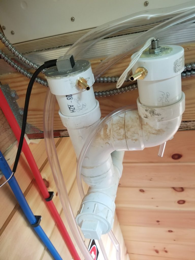
Done. There’s some sawdust and sticker residue I need to clean up from here, but this is them, nicely in place. I’ll talk about those brass fitting shortly.
I realized I may want to replace those sensors someday but there was no easy way to have them be removable while also maintaining a water-tight seal.
Remember, it is possible for the tank to get over-full, so it’s possible the water level will be above the “full” position on the sensors, so if the tops of these risers weren’t water tight, there would be leakage before the water in the tank made it to the emergency drain, which is a couple of inches higher than this. What I wound up doing was simply hot-gluing the sensors in place. This provides a low-pressure waterproof seal while being weak enough that if I were motivated (or used a heat gun — it might ruin the sensor, but if I’m taking it out, it’s already because it isn’t working) I can get the sensors out without changing that critical height for each.
So what’s with those brass fittings? Well, if I want these sensors to float in water that’s the same level as the tank, water has to enter these risers. It will, since they are connected to the tank’s manifold, but it only will if as the water in the tank rises, the air in these pipes has somewhere to go. Otherwise, they are effectively a diving bell, keeping a big pocket of air, preventing the water level from rising and being sensed. The air has to go somewhere. Why not just drill a tiny hole in the cap? Reason 1 – the gray water tank air is likely to be stinky. Reason 2 – if the tank gets over-full, water has to keep coming into the fill manifold until the manifold itself is full before the emergency drain will offer relief and it only relieves what comes in after the fill manifold is full (the tank is definitely full). Those little holes would become fountains. No bueno. Hence the fittings. These are installed at the very top of travel for the sensors to allow the air to escape. If the riser pipe should become totally full of water, due to the tank being over-full, the dribble out has somewhere to go that isn’t the floor. Where exactly does it go? Ironically, it will go into the kitchen drain which will eventually cause it to intermittently circulate via the lift pump into which the kitchen drain feeds, but if that’s happening, there are bigger problems at hand, not the least of which is the tank needs to be drained already!
So there’s the two little vent/overflow lines from the sensors (which are okay to tee together), the condensate and heat exchanger drains from the water heater, all needing somewhere to go. That’s a handful of tubing.
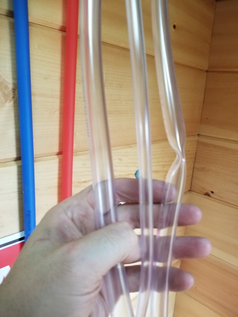
I think what I’ll do it make a special cap that has matching fittings for all these tubes, terminate them there, and run a single drain pipe from that special cap down to the kitchen drain line. This will keep things from being really bonkers in terms of so many tubes and will transition to a nice, big drain pipe sooner rather than later, for all of them.
Here’s the other end of those supply lines we were looking at in the loft. You’ll notice I did bend the red line here — and you’ll notice it does not track the blue line as it goes into the wall. that was the only way to do it without making too tight of a bend. This is all happening behind the fridge anyway, so it didn’t matter that it had odd aesthetics.
If I had thought about what was going to happen in the loft (I didn’t), I might have run the two lines further to the left so I could have two tracking bends up at the other end, without needing fittings. However, I also wanted to give enough running room after the cross-over that the two lines could once again travel tight against the wall. Could I have done that and had them both a bit more to the left? Possibly. But that’s not how it went this time 🙂
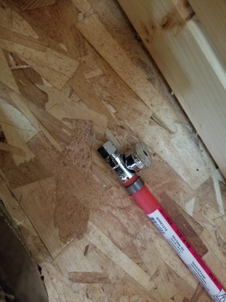
In preparation for the water pressure test, I did need to terminate those lines that head into the kitchen (left) even though I don’t know what’s going to be happening there so I can’t make those the final runs. Still, I can just temporarily attach some shut-off valves to the ends of the lines so I can do the test. They can be removed and re-used afterward without damage, so this is an easy and cost-effective approach.
Are we there yet?
Not quite. Getting close, though.
Rounding out this report, we have new brackets for the gray water lift pump, newly fabricated and installed:
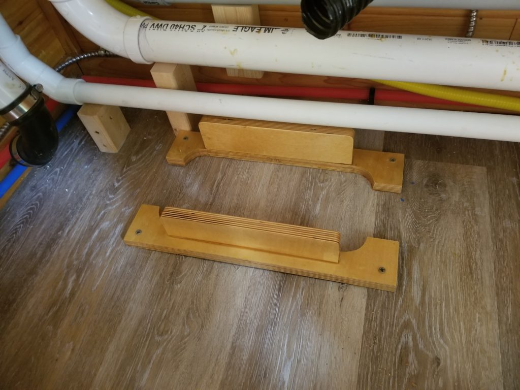
And once again, things are really close. You remember how tight the tub was against the pump body. These brackets hold the pump just exactly there. What will keep the pump from jumping while on the road? Well, there’s several pipes that come in at various points that should be sufficient to keep it parked in place. And then there’s the suspension of the trailer itself. Maybe I’ll put in a tie-down anyway 🙂
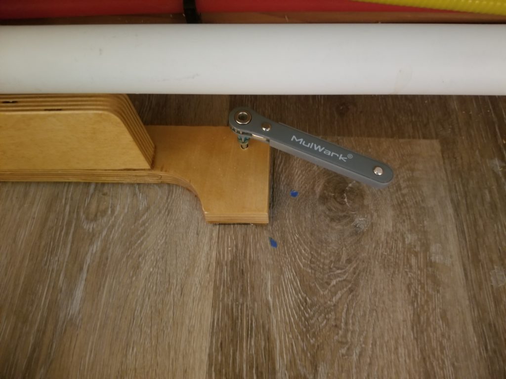
Per usual, there was just barely enough room for fasteners and tools. That little ratchet bit driver has proven to be an excellent investment.
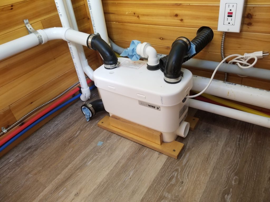
Installed. The white port on the top is the gray water exhaust, which will go up through that last hole in the ceiling as soon as all the sealing of the ceiling behind where it goes is done. It’s almost done now. Maybe one more round for the propane line.
I have a plan for the tub drain now. I’m going to use some flexible hose from the drain to that lower port in back (black rubber, blue rag, near water lines) to the tub drain itself. That will let me hook it up before the tub is fully in place and then just scoot it to its final spot. A hook on the wall will hold a section of that tubing a little high, creating a trap. I thought hard about what kind of tubing to use for this and ultimately settled on some remarkably expensive chemical-resistant stuff called Tygon. I figured this tubing will see tub cleansers and various personal care products for decades, so it had better be up to the task. I really don’t want to have to ever replace it, given the huge inconvenience of moving the tub, so the fact that this tubing was like $20 per foot, although hard to swallow, I think will be a good investment in future maintenance. I also only needed 5 feet of it. Sure, given the cost of the whole project, what’s $100, but it still made me cringe to spend that kind of money on 5 feet of tubing.
This is the bottom of the tub, with one foot replaced with a bolt.
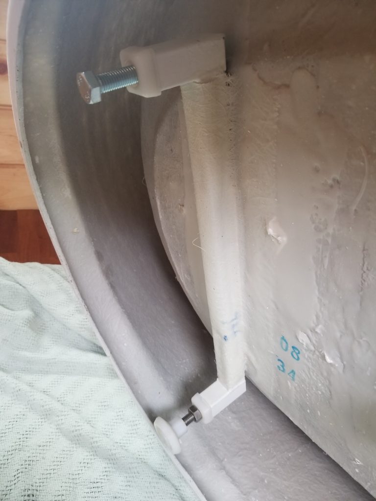
One thing I noticed was that the tub, while it has feet, has no way to secure it to the floor! That might not seem to matter, but it does. The feet can carry the weight and level it, but what keeps the tub from shifting and putting stress on its drain (if the drain weren’t a hundred bucks worth of fancy tubing, namely, how everyone else is going to be doing it)? I suppose one could put adhesive around the skirt, but that’s ugly and not likely to be super-effective, given how thin the skirt is. I’m baffled. I do, however, need to secure the tub to my floor. I also know that just putting some blocking around the skirt isn’t going to be enough – one can stand on the floor of the tub beyond where these feet are and cause it to tip! I need to really secure it to the floor, not just keep it from shifting.
My plan is to make some kind of runners and attach them in place of the feet. These runners will, in turn get screwed down to the floor. To do this, of course, I need some bolts that match the threads of these feet with which to bolt on the runners. Conveniently, the feet also had lock nuts, so I could just slip one in my pocket and bring it with me to my local home center to check for fit. M12-1.75 was perfect. Question is, do they have bolts in that size, or will I have to order a box of 100 online because I want four?
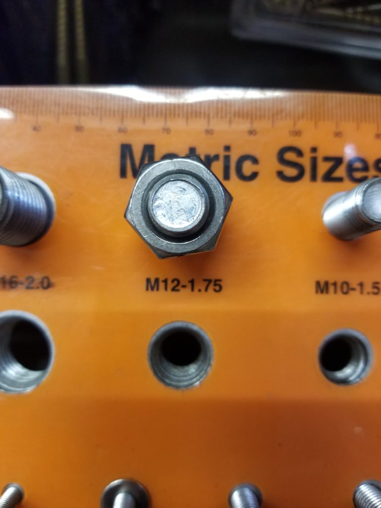
Answer: they have some! They’re a little shorter than perfect, but they will get the job done. I’ll build the runners later. They and the drain connection to the tub itself will be the last things that happen before the tub is installed. Before then, I need to finish the power system, both AC and DC sides of it, power it up, pre-charge the air side of the water pressure accumulator, turn on the water pressure pump, check for leaks (remedy if any are found), verify the pressure pump turns on and off properly. Then, when that’s all the way I want it to be, I can install the tub.
And then, I will have cold and cold running water. Not quite hot & cold running water, but an important second step and definitely more fun than cold and cold standing water, which is what I have today. Hot water won’t come til next year, when I hook up the propane regulator and get at least one of the tanks filled — and have at least enough of the kitchen propane plumbing in place that there are cut-offs for whatever appliances aren’t installed yet.