At this point in construction, everything depends on everything else, so it’s kind of hard to pick a single direction and go that way for a while. Instead, progress is incremental across a broad range of areas. Each one advances a little bit, then I come up against a dependency and have to move that forward enough to be able to finish the thing I was doing before. It’s that same old “before something can be done…” thing, but now it’s wider.
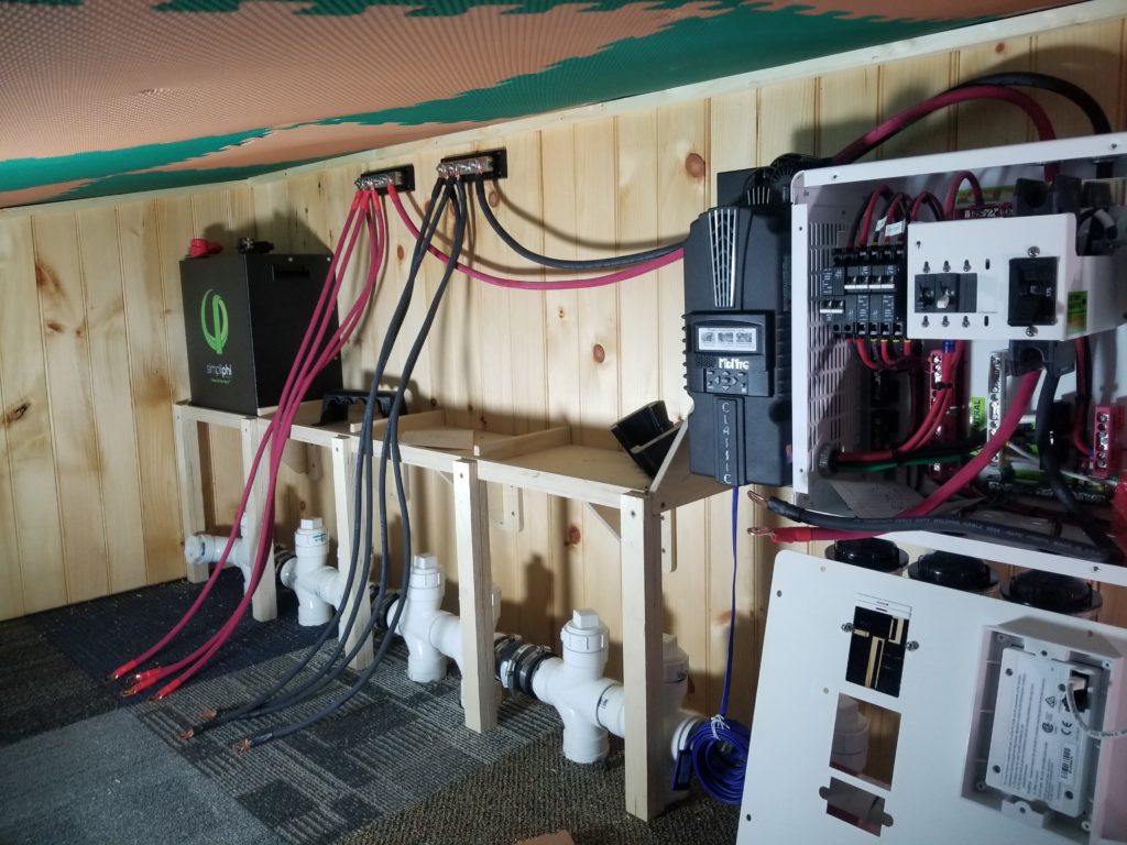
Recent progress includes the battery bank cables (red and black, center-left):
Before I could do that, though, I had to figure out how to get all four battery modules connected together safely. There’s a lot of energy in there and while under most circumstances, it comes and goes relatively calmly, sometimes there’s a heavy flow and the wires must be sized to handle it. So, too, whatever connects the batteries together… which also means figuring out what those things are called, and what the search terms need to be to find them and not also a zillion other things I don’t want. Terminal blocks? Bus bars? Sure, that’s what they are, but nearly everything in those categories is way undersized for this job. I finally found this guy, who is a couple of pounds of metal. Totally ready to handle a few hundred amps. For scale, those screws are 3/8″ diameter.
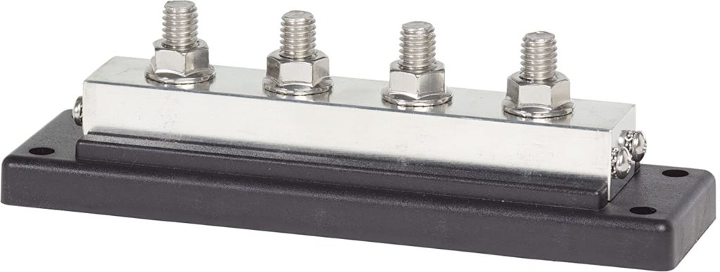
So while installing the bus bar wasn’t such a big deal, it took hours to locate the right part and that counts as work, too. Then figuring out how to attach the heavy cables to it is another thing. Obvious enough if you’ve done this sort of stuff before, but if you haven’t, well, there’s some time spent discovering. The answer isn’t wire nuts! The answer is this:
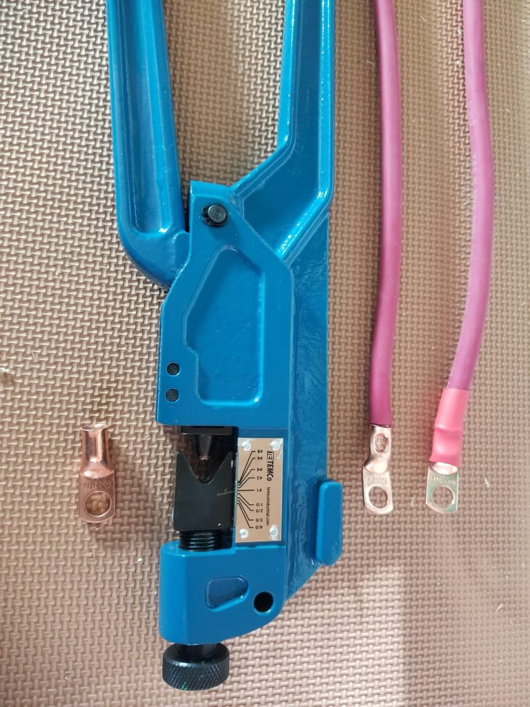
A massive cast-iron squeezy tool (it’s like 2 feet long!) that takes ring terminals (left) and deforms them around a chunk of wire (right) to the point where the wire is in there so tight that it won’t come out and it’s in full contact with the metal. Easy. Obvious, too, once you know that’s how it’s done. I had to find out first. Then scour the interwebs for tooling, reading reviews, etc., trying to find the right quality-price-availability combination. None of that looked like making or installing cables, but all if it is work that takes time. And then of course I had to wait for the wire, tool, terminal block, and terminals to arrive, all from different parts of the country.
Cables made. Now to hook them up to the power center!
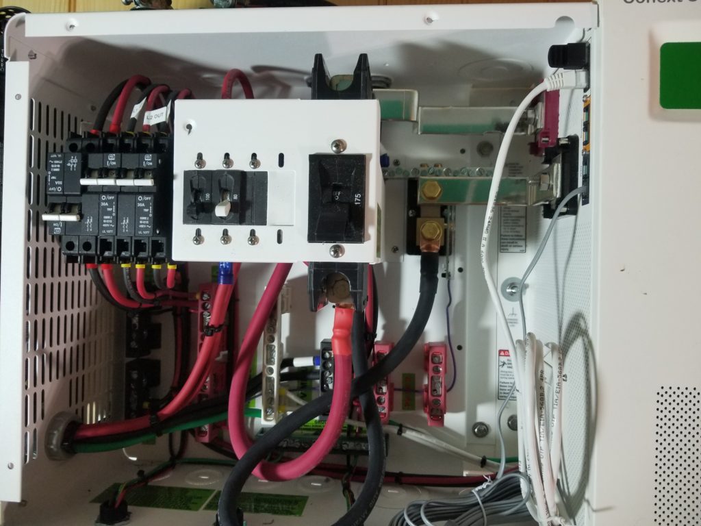
You can see the red cable attaching more or less dead center, below that big black thing. The black cable attaches to the gold stud to the right, in the back. That one was the easy one – just put an extender on my torque wrench and tighten it down. The red cable, though, that was another story entirely! It looks like it attaches from the front, but that’s actually the head of the lug. It attaches from the back!
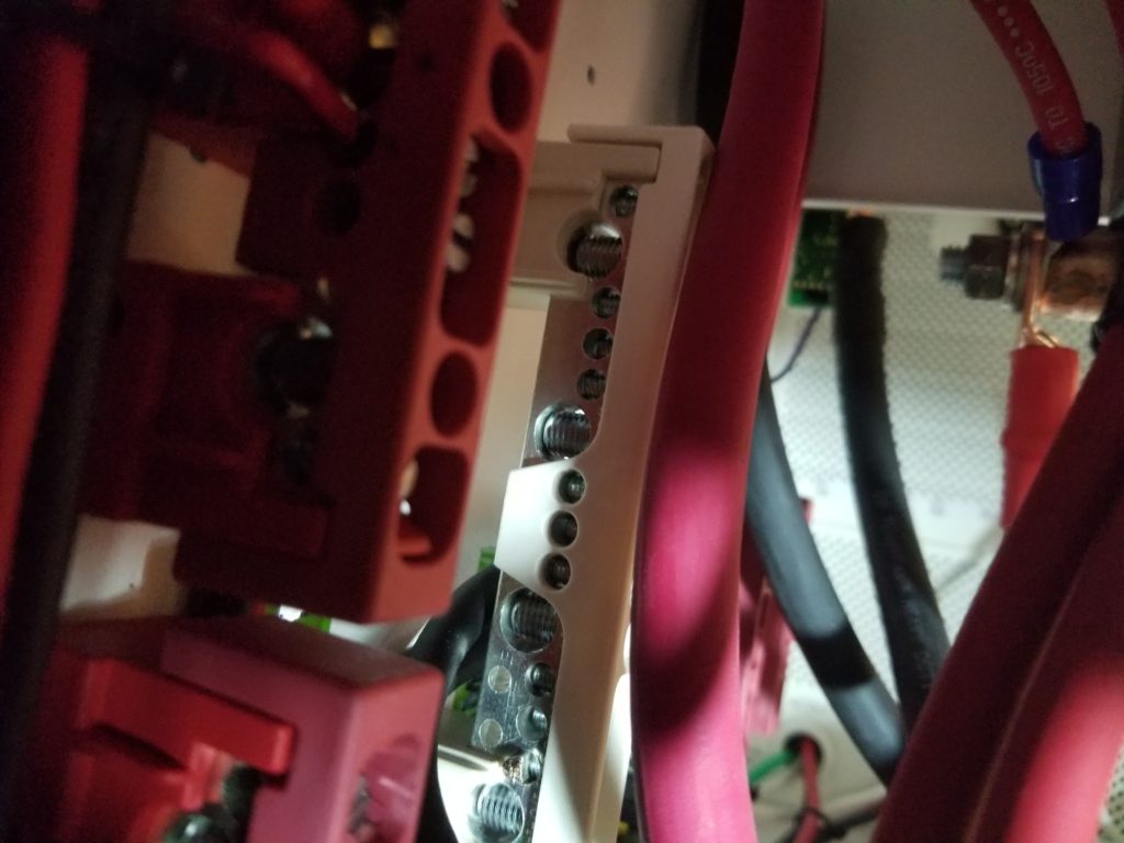
That’s him in the upper right corner, coming up from the bottom and sharing the lug with a thinner wire with a blue collar, going up from there. There’s just a few inches of clearance between the lug and the back of the cabinet and there’s 96% enough room for the handle of my torque wrench to get in there to tighten it down precisely. This photo is actually along the direction the wrench would have to approach the lug. Notice all the stuff in the way? No way to make this happen properly. I used an ordinary (smaller) socket tool instead, having roughly calibrated my wrist against the torque wrench when tightening all the other connections I could use it for. I don’t know what they were thinking when they located this connection here. Or maybe the answer is simply “make it as tight as you can with whatever you got”. And that’s what I did.
Okay, then, battery cables built, bused, and brought into the power center. I still need to hook up the AC in (for backup generator) and AC out (for powering the house!). And one more input, too, for the solar array. This power center is gonna get crowded. Happily, those cables won’t be as massive as the battery ones. Still, gonna get crowded in there.
In other news, some progress has been made in the plumbing department. I’ve finalized the design for the level sensors and tank-full interlocks. There’s almost nothing to show for it now, other than the leads from this float switch emerging from the fresh water tank, shown here.
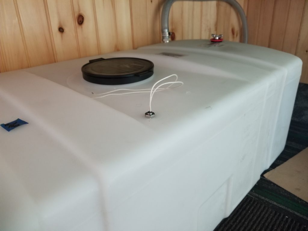
This is another one of those cases where things depend on other things. I know what those wires need to go to, but not where that thing will be or how they’re going to get there. That depends on a bunch of other things, yet to be built. But I know I need the float switch there, so it’s been installed. As the rest of the level sensors come together, it will become more obvious what their cabling requirements are and how to get all the signals to where they need to go.
Everything is slowed down by COVID-19, too. Simple stuff like a plastic pipe cap (into which a hole is drilled to mount the gray water level sensor, for example), was totally out of stock at my local HD with no in-stock date known. This is a $3 part that they usually have boxes and boxes of on any given day. I asked the clerk about the lack and he said supply chains have been disrupted considerably. So I mail-ordered it. One silly little plastic cap I should have been able to just buy off the shelf. Instead, I had to find a supplier, make an order, and then wait for it to arrive, which it did today, whereupon I summarily drilled yonder hole for the sensor, and am thus now ready to continue that little corner of the project, a week (instead of an hour) later.
There’s a lot like that going on now. Lots of waiting for parts that shouldn’t be this hard to get. And a lot of thinking about how things go together, how things get from point A to point B. Everything’s close to everything in the tiny house, which means nothing has to go far but it also means things get crowded easily and that must be taken into account.
Two more things for today’s update. First, I realized that the main entry door is going to have to open inward towards the coat closet. Opening any other way doesn’t make sense for the space. That means the coat closet door will get whacked by the front door if the closet door wasn’t properly shut. It could even prevent the front door from opening if left in an especially poor position. No bueno! Redesign! The coat closet will now have bifold doors, not a one of which is wider than 6″, definitely clearing the full swing of the door… but not by a lot. Solved.
Not quite! The keister coaster, if left in the sitting position, would also block the door’s full swing. Also no bueno! So I moved it from the coat closet to the wall next to the door (2x lumber and a little red level standing in for a real seat, yet to be fabricated, depending on cabinet door aesthetic choices yet to be made).
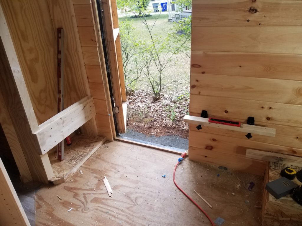
Which of course means that heavy block I put in place across the closet to hold up my own keister on the keister coaster is no longer necessary and will be removed. And that leaves gaps in the trim, which went around it. So I’ll need to re-trim it or fill the gaps, at least, which won’t look nearly as nice as re-trimming it.
What was that about way-finding? Yeah, this is that.
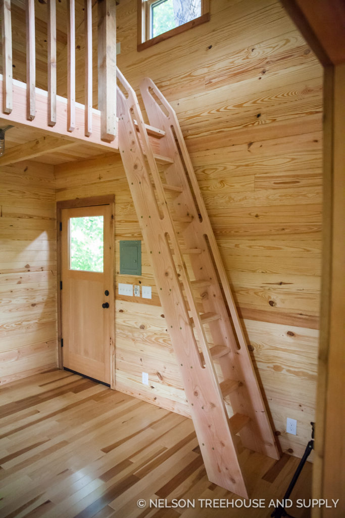
Speaking of way-finding, the other bit of news is that I’ve gone back and forth and round and round on how, exactly, to get to the Cozy Loft. I had this idea for pull-out staircase but there were logistical reasons that wasn’t going to work. Then it was a ship’s ladder. That would totally work — and I even found a design I really liked that wouldn’t be too hard to build (there’s even a video showing how it’s done).
But then there’s the question of where to stow the ladder when not in use. It has to get out of the way – there isn’t room to leave it in place full time. And then I came back to one of my original thoughts, a tansu staircase. That’s something like this:
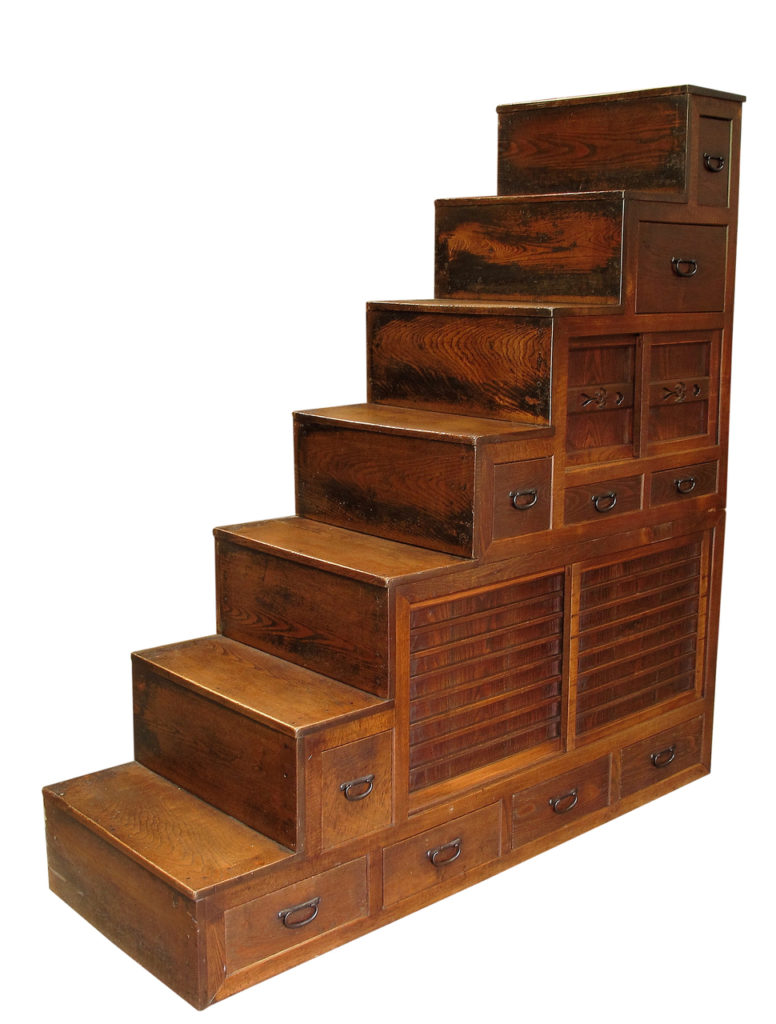
My previous reasons not to do this were (a) no hand rail and (b) all that volume where the body transits has to be left open for the body to transit. Unlike a ladder in the middle of the corridor (temporarily), where there’s no permanent claim to the airspace, whereas having a built-in stair like this reserves the airspace for people going up and down, when when nobody is going up nor down. That cuts in half (or more!) the total amount of cabinetry that could be on that wall. And that seemed like a big price.
It is. But I also realized that having cabinetry absolutely fill that wall would be a horribly imposing thing that would look terrible. It would sharply cut in to the open feel of the space, making it very crowded-feeling. That airspace needs to be left open or decorated with flat art (paintings, photographs, posters, etc). As for the hand rail, I can use a simple hospital-style one — just a smooth board stood off the wall a little, such that a person could slip their fingers behind or grab for stability. Totally do-able.
The tansu stair would follow this profile sketched in blue tape on the wall. The straight line is the hand rail. It’s not a ton of cabinetry below those stairs, but at 26″ deep, it’s more volume than you might think. Most importantly, it leaves a decent amount of open space in the atrium (middle section) of the house. The cozy loft will look out over open space and the BeDeLiA will be closed in a bit, but still have some view of open space, too (and it has three windows anyway). Having the BeDeLiA closed off some isn’t so bad, actually, to help give it a defined sense of place.
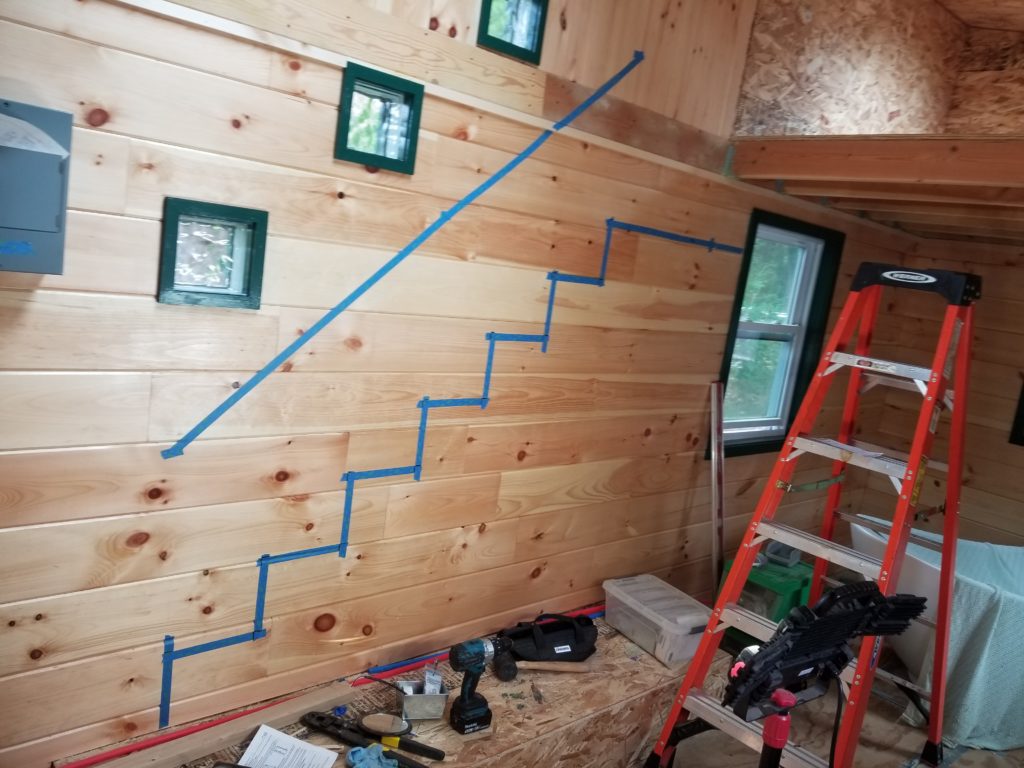
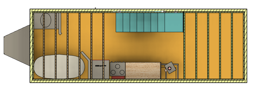
For scale, those stair risers are a more-or-less standard 8.5 inches and the treads are 9-3/8. Almost normal stairs. And now the angle and position of the light ports (little square windows dressed in green) makes sense again. They were laid out there to follow the original staircase design. Full circle back again!
Update 2020-06-30: Here’s what the volume of the tansu stairway looks like in the computer model.
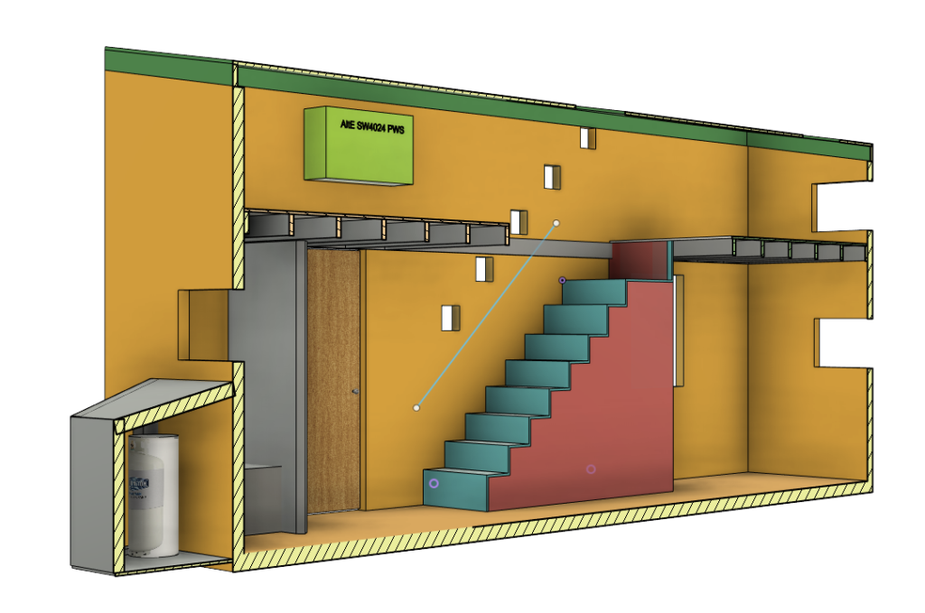
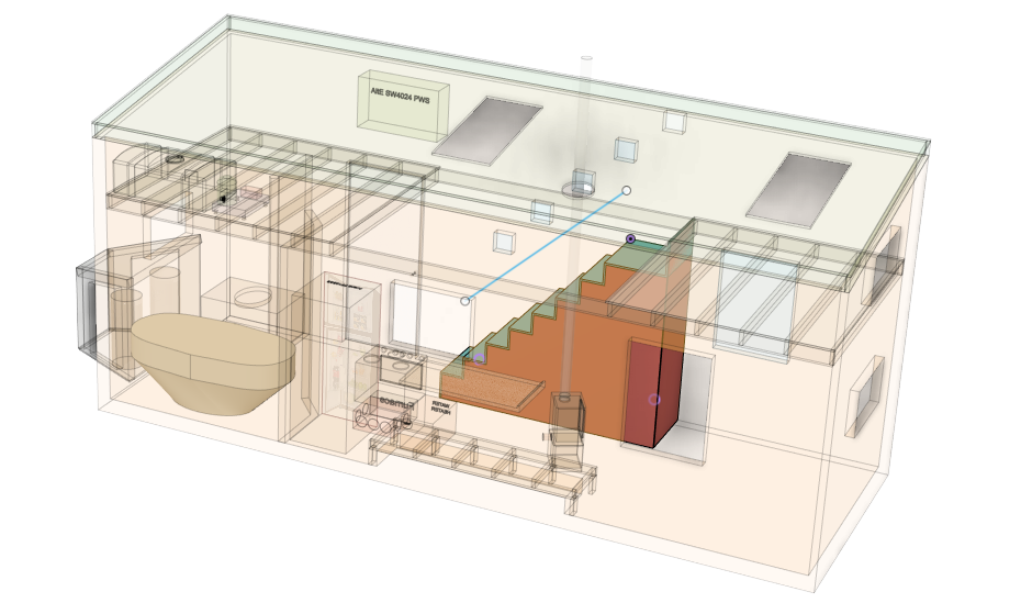
And from the top, to see how much floor space it commands and how it affects the kitchen. It looks like there’s still a decent amount of room to move around. I think it works.
