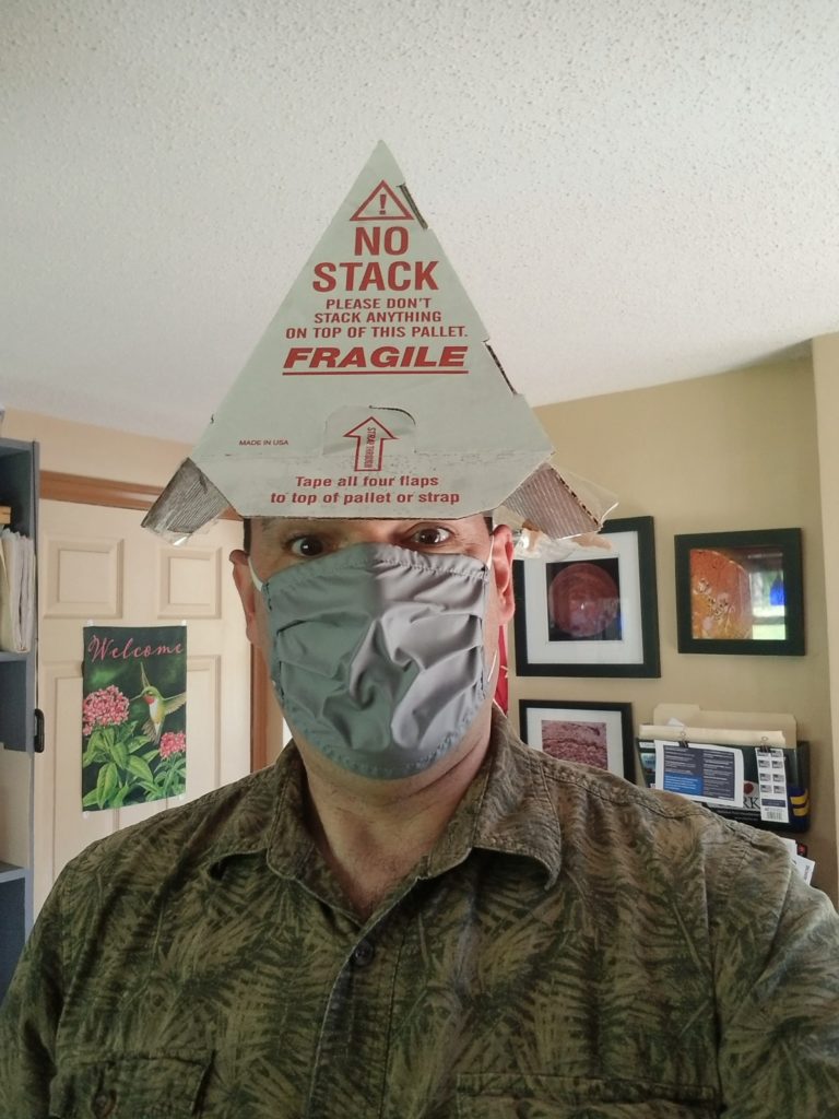
A few days ago, the power center arrived by common carrier.
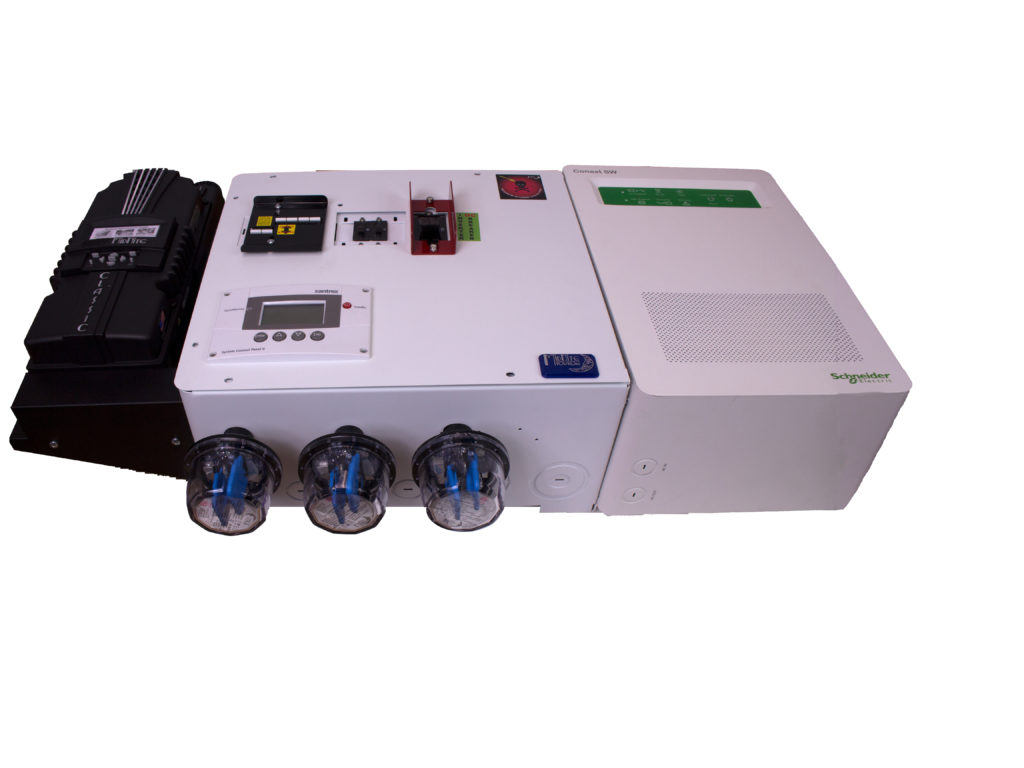
And when I say “power center” I mean this thing which is really three things.
On the left, a device to tame the wild voltages and currents from the solar array such that the batteries may be safely charged by it.
On the right, a 4kW inverter which can take DC from my battery bank and turn it into a lot of AC to run appliances, my well pump, that kind of thing. In the middle, interconnects, control panel, circuit breakers, other protection devices, and a place to wire it all together. Power center.
Here’s the thing: it’s heavy. How heavy is heavy? It’s 120 pounds. And it’s bulky – three feet wide, almost a foot thick. And I wanted to get it 7ft up in the air onto the deck of the Storage/Utility Loft. No way can I lift it directly overhead like that (I’m not 18 any more)… so what to do?
I thought about just carrying it up the ladder. Noooo. I’m not certain my ladder could take the 360 pounds of me + it, for starters, and for sure I can’t keep my balance while carrying 120 pounds of cargo trying to ascend the ladder. Okay, maybe a two stage approach?
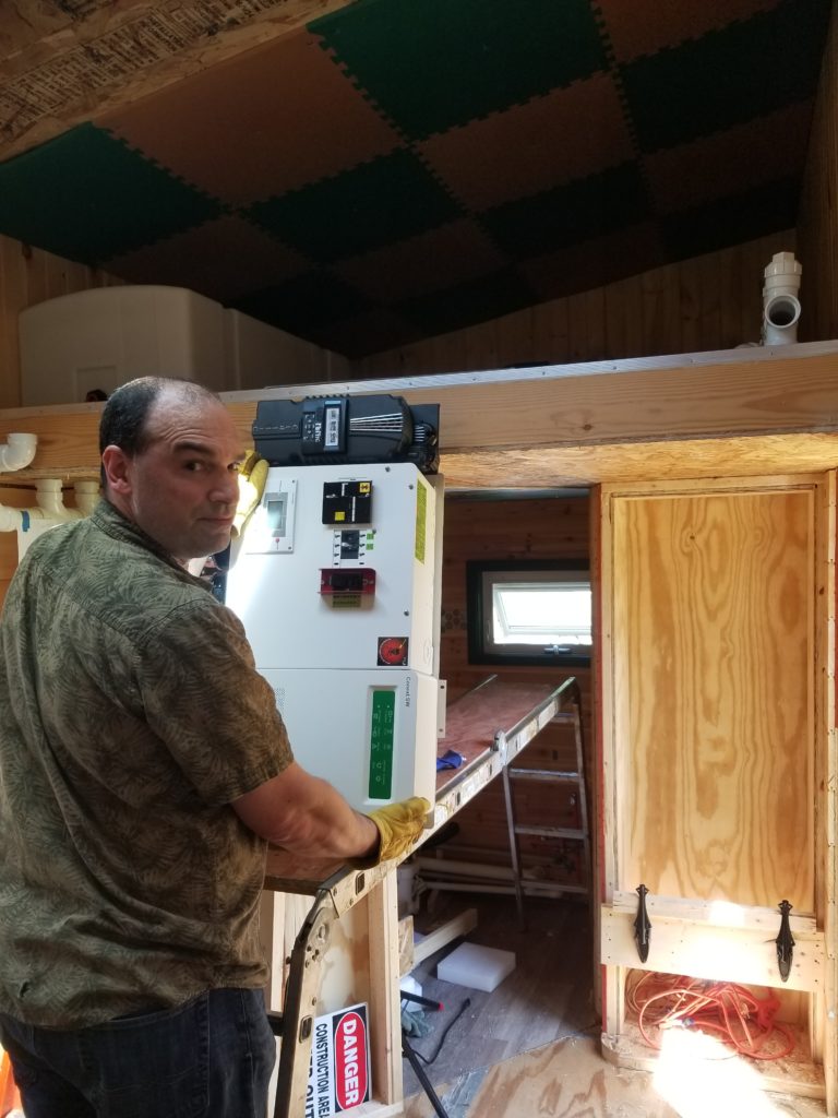
Maybe I could put my ladder in scaffolding mode, lift the power center onto it, which I can do, since it’s a reasonable height, then get up there with it and finish the lift to the deck. It’s not that far…
Seems like a solid plan, yes?
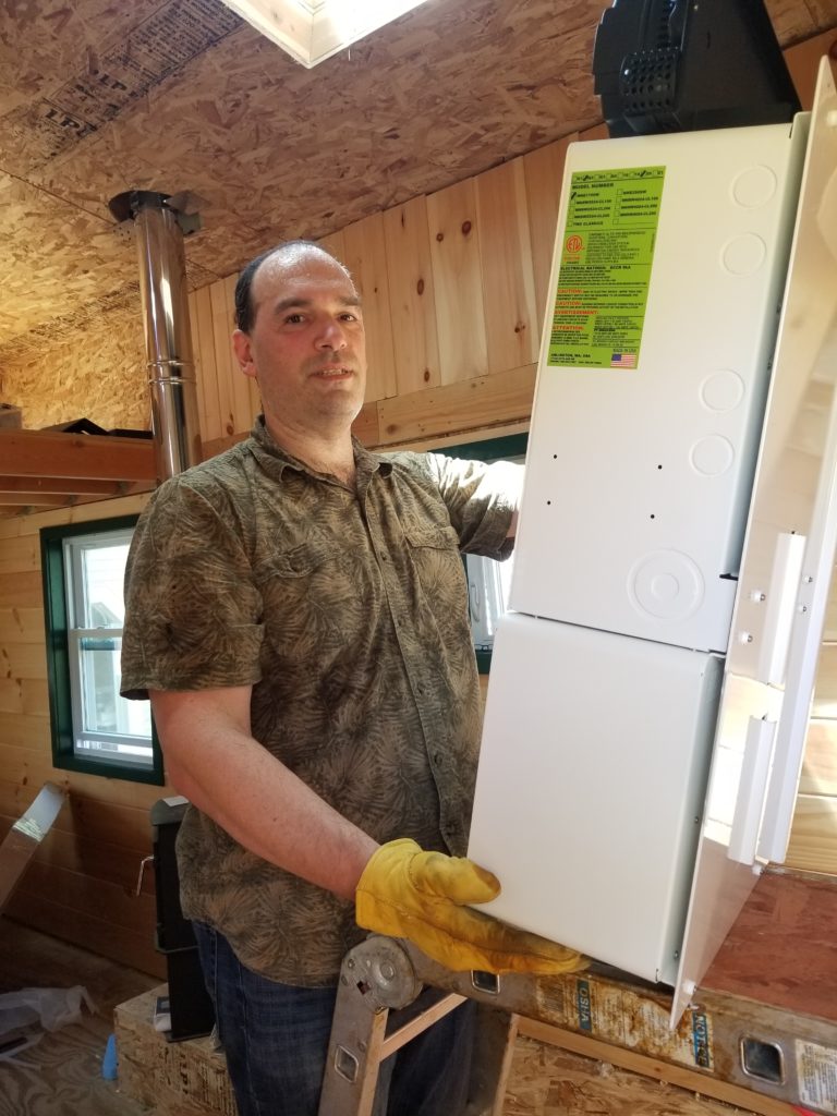
Remember this thing weighs 120 pounds. I can lift it fine but not also control both it and myself ascending even what is now a very short ladder… and no way the ladder in scaffold mode could take the 360 pounds of it and me if I got up there on the deck and even if I did, there is no sane way to do a safe lift from up there. That’s a trip to the hospital and damage to a $4000 piece of equipment waiting to happen.
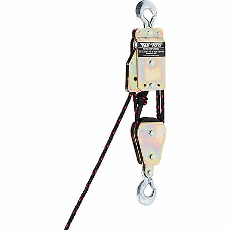
I am not at all keen to have either of those things happen. I thought through plans B and C and none of them were appreciably more likely to succeed without incident. What I need instead is either two more strong helpers (difficult to come by in these days of COVID-19) or some basic rigging apparatus. So I ordered one.
I would imagine such a thing to be quite useful for getting other bulky items up to the SUL, so I really don’t mind spending a little money on it. Okay, then, power center has to wait until the block-and-tackle arrives. Something else to do, then. How about a shelf for those battery modules?
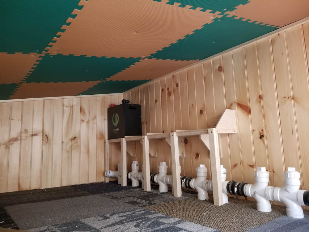
Sure. I can do that. The modules, one of which you can see in the first position, are about 13″ wide, 8″ deep, 16″ high and weigh nearly 80 pounds each! The shelf has to be pretty massive to take the load. The shelf itself is made of 3/4″ thick cabinet plywood. The brackets are centered under each battery dock and made from 1/2″ cabinet plywood, where the bracket angles sit in a groove on the wall plates into which they are both glued (wood glue is stronger than most wood if used correctly) and screwed (so is metal). There are six screws for each bracket into the wall which is 3/4″ pine on top of 7/16″ OSB, plenty to grab. After building the shelf, I propped myself up on it, putting maybe 200 of my 245 pounds on it as load in one spot. It held just fine. And it better: four batteries at 80 pounds each is … 320 pounds! Hm. Maybe I should add some more bracing. And what if the trailer — this is a trailer — hits a bump? Yeah, better add more bracing. So I added more bracing. Five fairly serious auxiliary legs provide significant additional strength. Yeah, that’ll hold 320 pounds of batteries, even if it goes bump. Those wall plates for the brackets also bear the rear of the shelf directly, effectively forming a cleat, too, making for more betterer strongerer. At this point, I could probably have just installed a long heavy cleat on the wall the massive front legs, but I already made and installed the brackets (thinking originally they’d be sufficient), so I might as well leave them. Removing the brackets would leave me with holes in the wall and unoccupied grooves in the bottom of the shelf itself, weakening it a bit anyway.
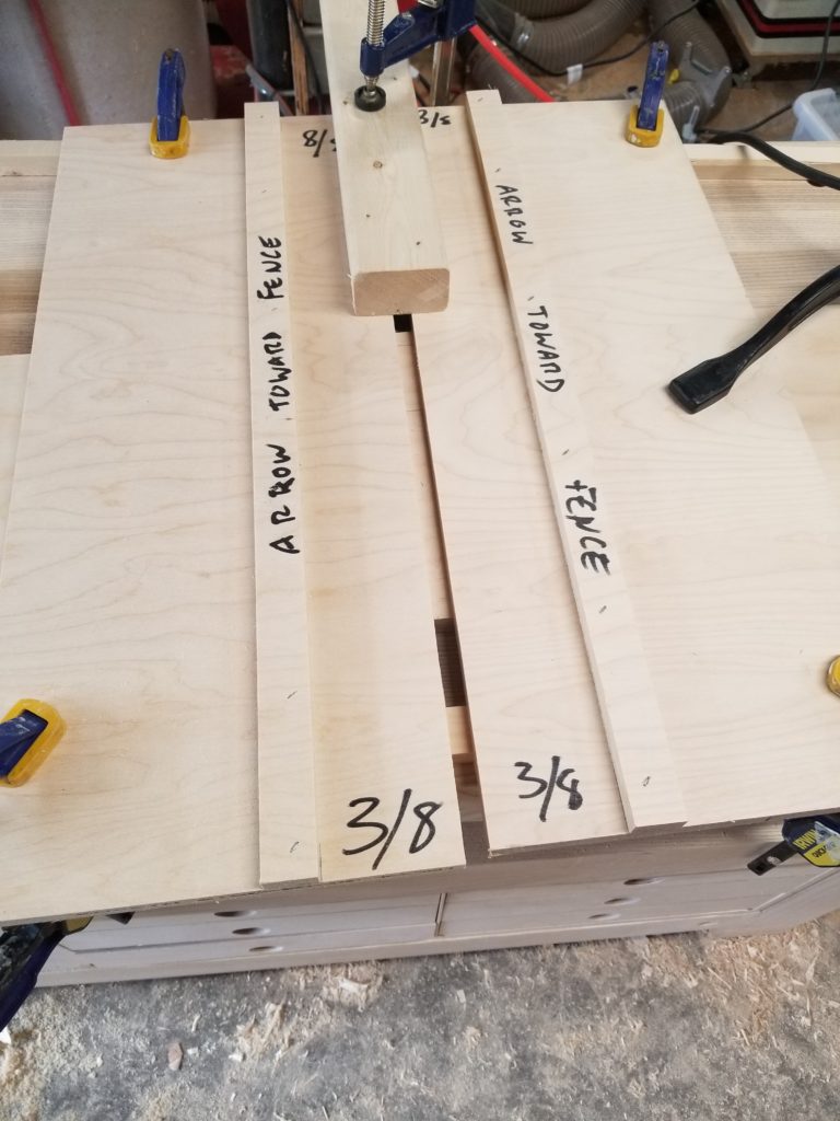
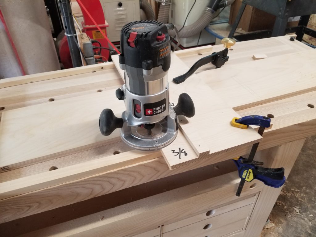
Shop Note: To make the grooves for the bracket angles in the wall plates — and in the bottom of the shelf to locate them — I made a nifty router jig I learned about in a book. It is simplicity itself, but nevertheless ingenious. It consists of two boards, each with a rail (a “fence”) attached to it. Shown here, two are side by side, ready to use.
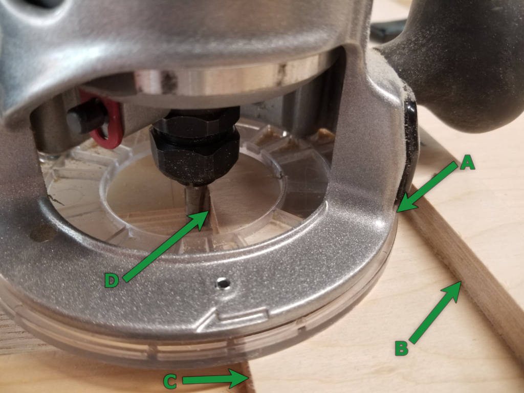
Here’s how it works. Shown here, with just one of the two jigs in place, you can see how the position of the cutting bit (D) is governed by the position of the fence (B) against which the router base (A) slides. The edge of the cutting path is perfectly aligned with the edge of the board (C) so if you want to cut along a line, all you have to do is align the edge (C) to the line and use the fence (B) as a guide. Presto, you cut along the line perfectly, every time.
Say you want to make a groove that’s exactly as wide as a piece of material so the material fits perfectly in the groove. If you use two such jigs as these and space them apart using a sample of the material, you now have left and right guides for its exact thickness. As long as the cutter bit is not actually bigger than the groove is to be wide, you’re golden. The right jig defines the right edge, the left jig defines the left edge, and if there’s any material to cut between the two, just float the router between the fences without fear. It will be constrained to the desired dimension.
So how did the edge of the jig get to be exactly aligned with the cutter? Simple! Make the jig a little wide, then use the router against the jig’s own fence to cut the base plate of the jig itself. Presto – a cut that is exactly where the cut is. Now the edge of the base plate tells you where the cutter went – and where it will go every time.
Here’s a further-out view of the whole operation, with one side removed so you can see all the things. The right side jig is in place to guide the router. The wide board in the middle of the bench is what’s about to get its groove on. Clamps hold the jig and the work in place. A little gap in front of the work piece gives the router a place to start before engaging the cut.
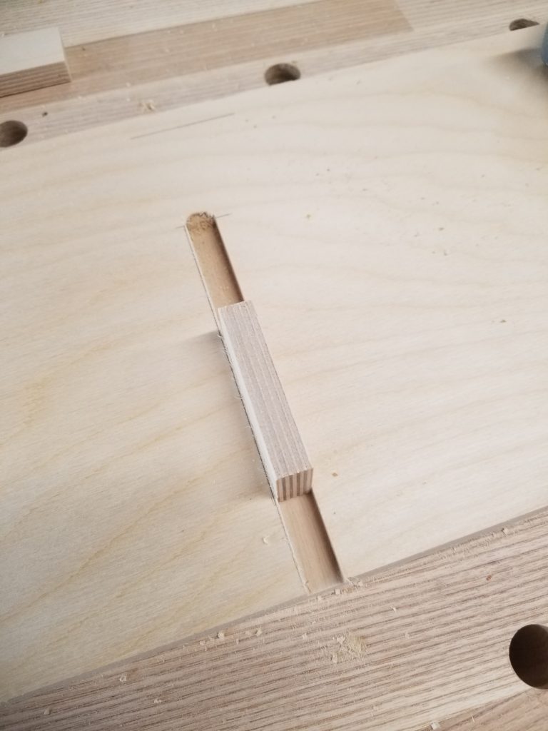
So does it work? It works. Perfectly. The pencil line was approximate but the groove itself is exactly the right width for the block. To set the jigs for this groove, I just put a block between them, closed them in tight, and clamped it all down. Remove the block and the jig is ready to go. Simple but ingenious. Perfectly sized cuts based on the material itself.
There’s more going on this weekend than just the battery shelf and not installing the power center, though.
For one, it’s a little thing, yes, but it really makes the space look nicer: some basic crown trim for the SUL.
It was also time to dress the foyer ceiling, which has been raw OSB for a long time. Step 1, make a template of the exact shape. This is harder to do than it looks, since the heavy paper doesn’t go where it’s told and tends to want to just fall down of its own weight. There are some tape loops behind it to help it stay aloft… but you don’t want to have too many of those or it becomes impossible to remove the template without damaging it.
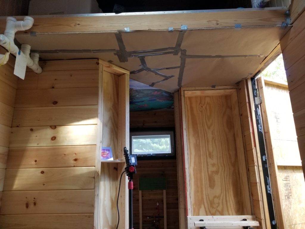
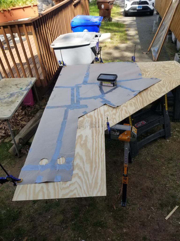
Step 2 is to lay the template out on some plywood and trace it. Hey, that shape looks a lot like the shape of the mural! Indeed it does. It is the negative of the mural, in fact: it’s what was left after cutting out the panels for the mural in the first place. Naturally, it’s going to be about the right shape to complete the ceiling.
Why is the templated area so much smaller than the wood? Doorways, pantry, coat closet, to name a few. Step 3: cut. Step 4: attach to ceiling.
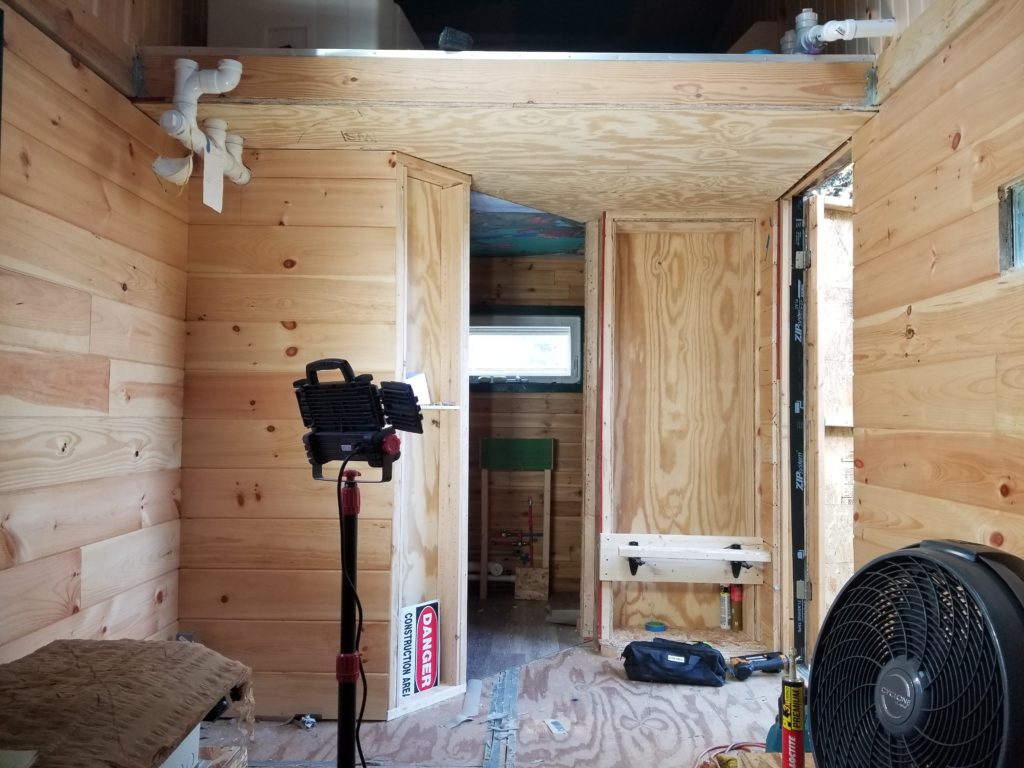
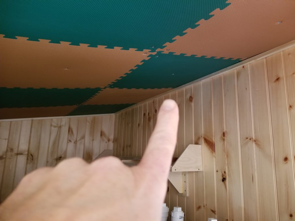
And there it is, the foyer ceiling, now with clothes on. Better be careful with the fasteners: 7/16″ of an inch of OSB in the ceiling is followed by the in-ceiling gray water tank! I definitely don’t want to pierce the tank with screws or staples. Half inch staples and some construction adhesive to the rescue. Yes, a half inch is ever so slightly longer than 7/16, but remember to include the thickness of the boards I’m installing, too. It clears. And the pipes are not literally resting on the other side of the ceiling, either. While I was in no particular position to forget this critical fact, I am nevertheless quite happy I remembered it. No long fasteners into the ceiling!
There are two other minor things you can see in this photo that weren’t there at last report. First, you can see the shoe-tying seat attached to the front of the coat closet. The seat right now is just a piece of 2x lumber but the important parts – the fold-down brackets (black) and the mounting board (behind them) – are in place. The seat itself will be considerably more beautiful… later. Right now it’s just a scrap of wood so I can park my keister as I contemplate things. The scrap is just loose there and probably not sitting straight, and may itself be a little bendy for that matter, hence the illusion of it not being level. Also the photo itself is not perfectly level as taken, either. The seating plane is definitely close to bubble-level in real life.
In the upper right corner, you can see a pipe going through the wall to the right. What’s that? It’s the gray water tank vent / overflow. It goes to a grille on the side of the house.
Meanwhile, now that the mural is in place, I can finalize the conduit chases that go through the T.H.R.O.N.E. Room ceiling. There’s a lot here and there’s one more to go, which connects the graywater lift pump (white box) up to the graywater holding tank (upstairs). That will wait just a little while longer, until the lift pump has its final mounting location, which waits until the tub position is finalized…
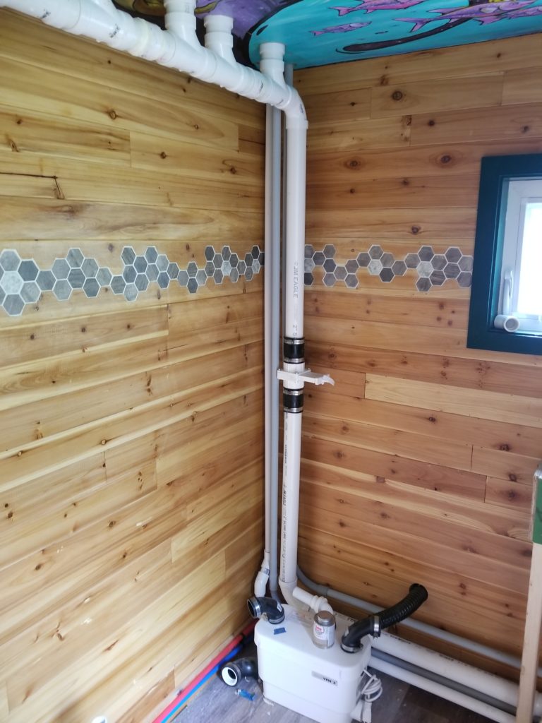
…which waits until the propane line to the kitchen & water heater is run, the shower controls are installed, and the final drain plan for the tub is established (connects to rubber elbow at the bottom, with the white insert). Before anything can be done… well, you know.
