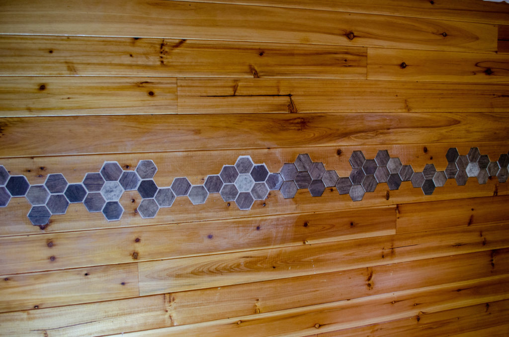
It’s been so long since I’ve done any tile work, I’d forgotten how the addition of grout makes the project come alive. Wow. What a difference! Also, it does a fine job of concealing rather a lot of imperfections.
The haze around the tile work just means I need to let the grout dry and go back after it and scrub it clean. Or at least I hope so. I did a second coat of the interior finish the day before – if it didn’t cure well enough, it’s possible the just-after-grouting cleanup activity may have embedded some grout in the not-quite-cured finish. If that’s the case, or if what I’m seeing here isn’t grout particles but rather micro-scratches from the sand in the grout, then I’ll need to buff it out with some steel wool and re-apply some finish to make it pretty again.
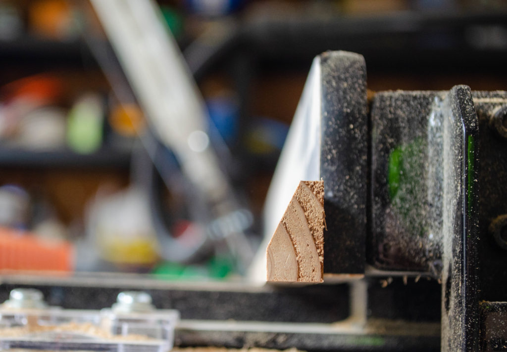
When your room has corners that aren’t 90 degrees, you need to make your own trim. Shown here, trim for a 130-degree inside corner, in process. To dress the corner nicely, that 130 degree joint is met by an opposing pair of 65 degree bevels. Kind of the opposite of a miter cut, if you want to think of it that way. Of course, most machine tools won’t cut at 65 degrees. That’s way too shallow an angle with respect to the work surface. The answer is to turn the work on edge and use the complement of the desired angle. 90 – 65 = 25. The table saw is happy to cut at 25 degrees of bevel.
So, to get trim for a 130-degree corner, that’s two passes at 25 degrees. Of course it is. 25 + 25 = 130, right?
Well, yes, actually. In this case it is 😀
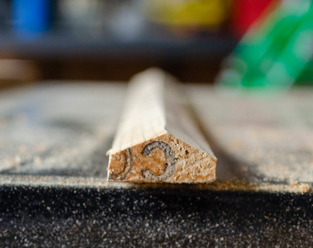
Here’s the 130-degree inside corner trim piece after fabrication.
By the way – all of the trim pieces are made from scraps from the interior planking and in some cases, scraps of exterior siding (machined rather a lot, since they start out 3/4″ thick and 5″ wide).
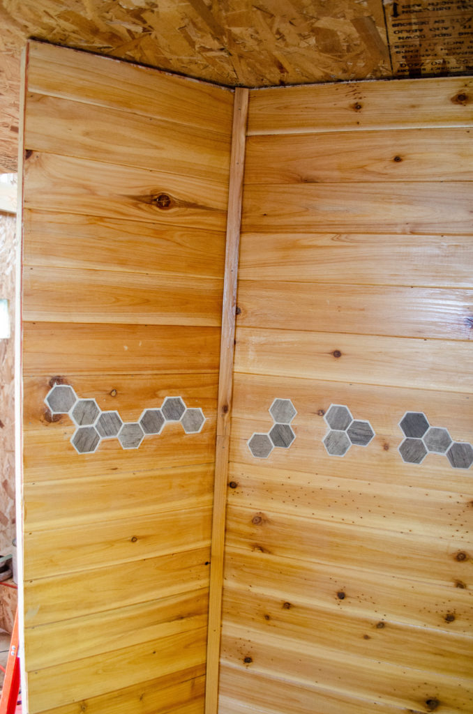
And although it doesn’t actually look so far from square, here is that 130-degree inside corner, all dressed up with that trim piece I made.
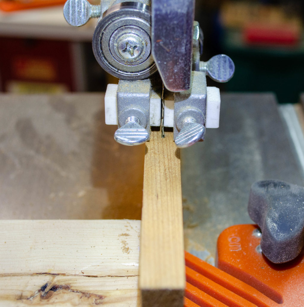
Speaking of making trim, one must start with some thin stock when making trim for *outside* corners. I didn’t have any thin stock, so off to the band saw we go to turn a 1/2″ board into a pair of scant 1/4″ boards. I didn’t bother to sand the inside faces smooth – they were going to be flush against the wall anyhow where nobody would see. This single board, a few inches wide, turned into two thin boards, each of which turned into three strips. Those strips each had – you guessed it! – a 25 degree bevel on one edge. This created a 130-degree miter joint when butted together.
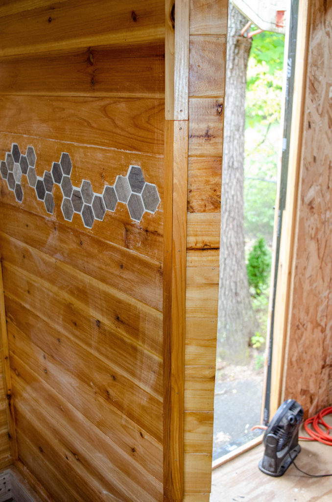
Yonder 130 degree outside corner, dressed. Yeah, that wall to the right is all of 3 inches wide, maybe. But stubby as it is, it had to be there, and at that angle, for the bathroom doorway to make sense.
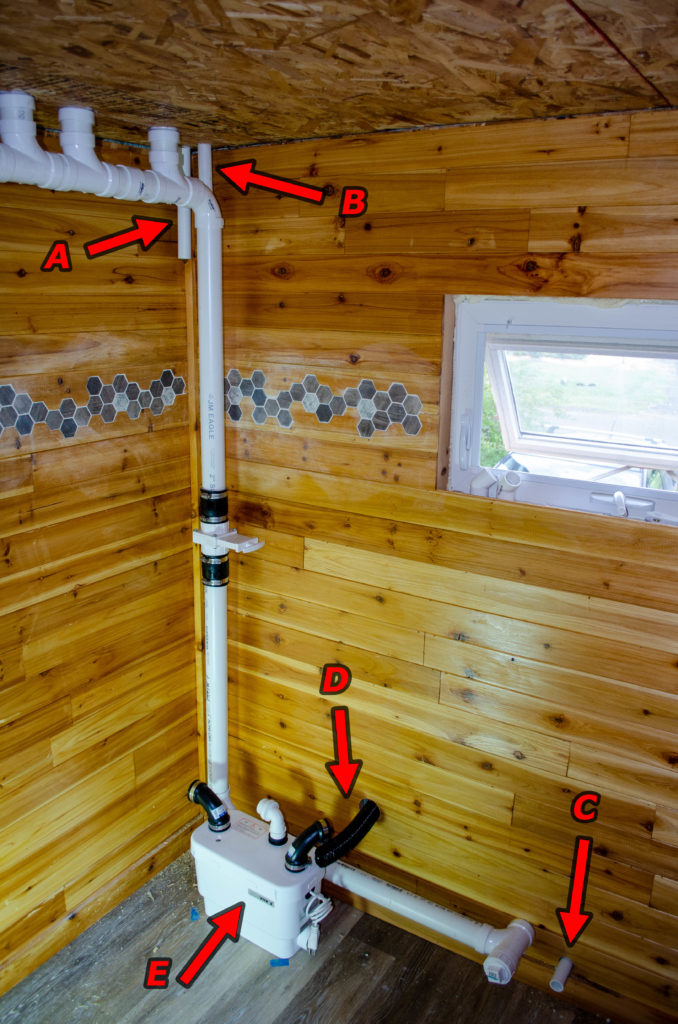
Meanwhile, now that the walls are all dressed up, I can finally get on with some of the interior plumbing work. The white box (E) is the gray water lift pump, a/k/a the bilge pump. My original thought was to hide this in the T.H.R.O.N.E. bench (which cannot be seen here but exists to the right of that window). However, I realized that the piping could be somewhat less intrusive and in fact easier logistically if the pump were in this corner. It turns out that the end curvature of the bath tub, which will live against the wall to the left of this frame, is such that the pump actually tucks nicely in beneath it, into space that would otherwise be totally wasted. As a bonus, having the pump not in the T.H.R.O.N.E. bench means (a) it’s easier to service and (b) the compartment in the bench I was going to use for it can now instead be used for something of greater utility to humans such as storing TP or other supplies for the bathroom.
So, what else is here?
A – stub representing fresh water inlet riser. Fresh water will enter the house through the Propane Porch and comes in to the bathroom at position C. This will be connected to A later, once the finished ceiling is installed (which must happen before actually attaching anything to A).
B – stub representing gray water riser. This will ultimately feed into the in-ceiling gray water tank. The pump (E) will feed this riser starting with that white elbow fitting on the top of the housing. Again, no connections through the ceiling will be made until the finish ceiling is in place.
D – vent for pump chamber. This is necessary so air displaced by incoming water has somewhere to go — likewise when the pump operates, air will be drawn in to replace the volume of water.
I found the perfect vent fitting (it’s actually intended for use with RV battery compartments!) to use, but it turns out the hose to it is 1.75″ ID. This doesn’t match up with ANY residential plumbing fittings. I will need to create an adapter that mates with the 1.5″ ID elbow and the 1.75″ ID hose. The easiest way for me to make that is to simply 3D print it.
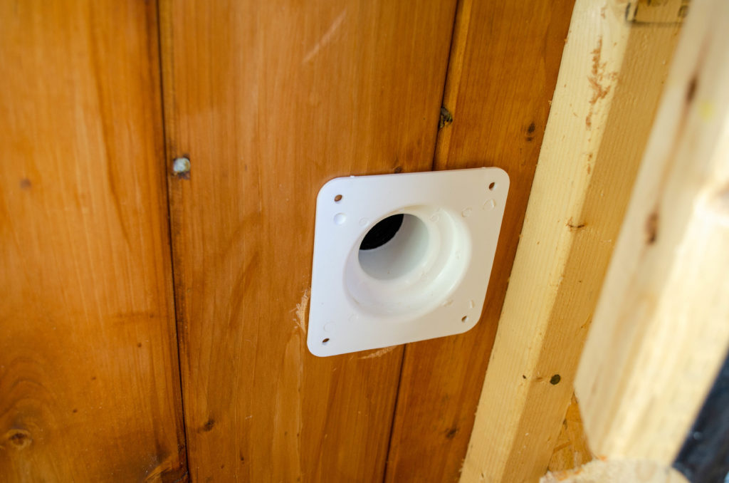
Here’s the outside portion of that vent, at the other end of that black hose. Notice the stepped profile of the interior? Yeah, about that. Because I didn’t want to drill a larger-than-necessary hole through the wall, I drilled one just big enough for the black hose. However, at the last half inch or so, the hole needs to be bigger, to accommodate that stepped profile.
The problem here is in two parts. First, it’s super hard to enlarge a 2″ hole into a 3″ hole when there’s no meat in the center. Free-handing a hole saw is not for the faint of heart! The second problem can be understood when you look at that stud along the right hand edge of the frame. Remember: the Propane Porch is toed in. It’s impossible to actually get the drill in position here, never mind the enlarge-an-existing-hole problem.
Aside from the toe-in problem, had I been really thinking ahead, I could have used a long drill bit to project the path of the vent from the bathroom to here, then gone at it from this side with the larger hole saw first, then to get the step and complete the bore, continue with the smaller hole saw following the same pilot hole. Repeat with the smaller hole saw from the inside and meet in the middle. Sadly, I didn’t think of that until a month later. — DBS 2019-10-12.
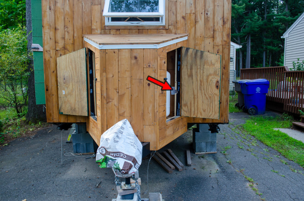
This is what I mean about the toe angle. The red arrow points to the location of the vent. It is quite intentionally at the extreme edge of the porch. This keeps it out of the way in general and conveniently corresponds to a nearly ideal location with respect to where the bilge pump goes in the interior.
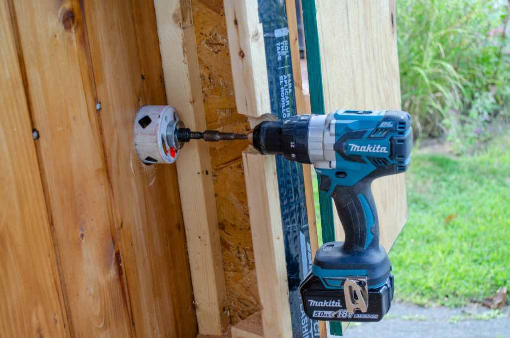
So how does one accommodate the toe angle of the wall when a straight shot with the drill is simply not possible? Easy! Cut a notch for the drill’s nose!
Even that wasn’t enough, though, as you can see now the hole saw’s shank is a couple of inches shy of the drill’s chuck. I had to use an extender here to make it reach.
And then there’s the important matter of the hole saw’s pilot bit having nothing to drill into, meaning there is no solid center refrence for that 3″ hole saw. What to do? The existing hole is like 5″ deep – I suppose I could have put a piece of square stock (which I’d have to fabricate) that just exactly fit, then brace it somehow on the other side without damaging the wall (A t-bar of some kind, braced against the floor would do it), so the bit had some purchase. Or, I could put a heavy leather glove on my left hand, use the speed control on the drill to oh so very slowly turn the hole saw *cupped in my hand* to create a starter groove to locate the hole, then run the drill at full speed. It wasn’t pretty – the hole saw jumped a few times as can be seen by scarring on the wall – but it didn’t have to be pretty, either. This ultimately worked but for sure this maneuver is not for the timid!
Never fear. That stud with the big notch in it is not really structural. Its job is simply to frame the door opening. Even with that chunk taken out, there’s plenty of strength left in the system to hold up a simple plywood panel door.
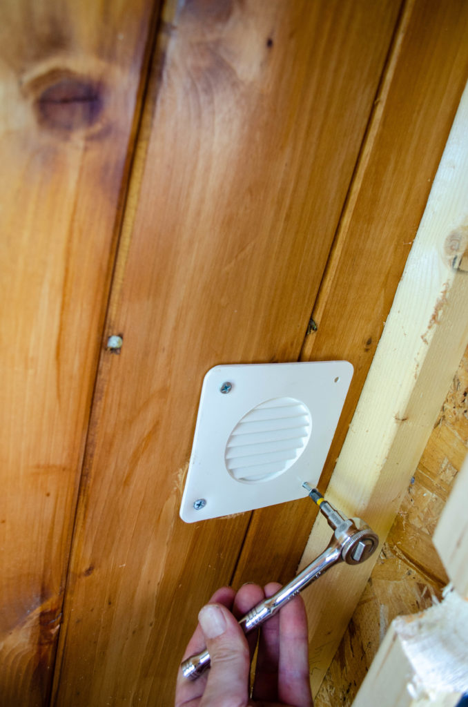
Once the recess was cut, it was time to install the cover. Of course even with that notch (which is centered on the hole, too far off-angle to use for driving the screws), there was no way to get a proper screw driver in here. Even a stubby one would have been a huge bother given the angle. My small ratchet tool with a 1/4″ socket and a P2 bit was just the right answer.