As I’m boarding up the interior, I have been using the router with a flush trim bit to make the window openings in the boards. This works great when there is framing around the windows, which there is for ordinary windows. However, there is NOT for these light ports because the glass blocks are as thick as the wall, making them essentially flush with the interior face of the studs. That means there’s nothing for the flush trim bit to trace against.
Hm. What to do? I know better than to try to measure the position of the light ports and cut them using dead reckoning. Things always sit differently than you think they do and almost without exception, holes cut this way do not line up with the things they are holes for.
Okay, then, how can I arrange to use my router to trace this outline when there is nothing sticking out that I can trace against?
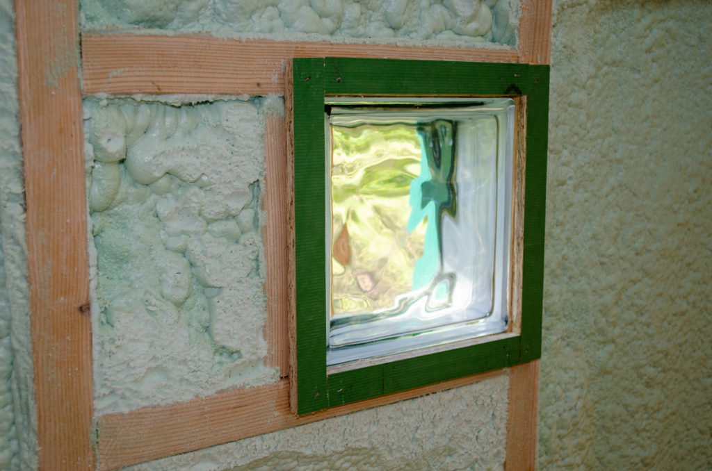
Answer: put something there that I can trace against! The green strips are just enough for the router to follow. All I have to do is *temporarily* install the board — hold it in place with a few staples — run the router to trace this little frame, to cut out for the window, remove the board, remove the frame, then install the board for real. Seems easy, right?
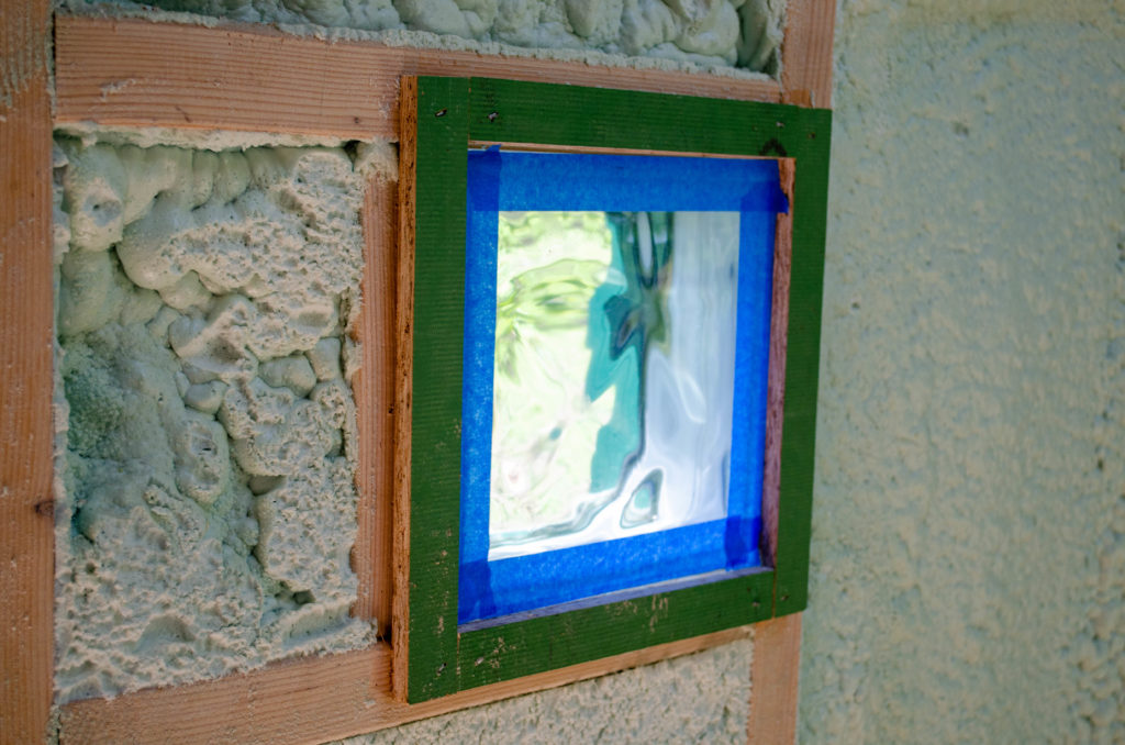
Well, before I start with the cutting, it occurs to me that the router bit is going to be VERY close to the glass. I’d better tape it off so the bearing of the bit doesn’t scratch the window.
Okay. Ready!
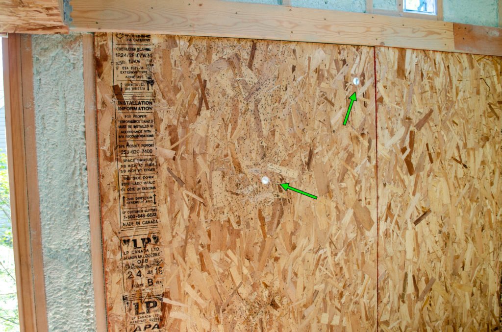
Not quite ready. Almost ready. Remember the mantra: before anything can be done, something else must first be done. In this case, starting holes for the router (green arrows). These were cut before the board was put in place.
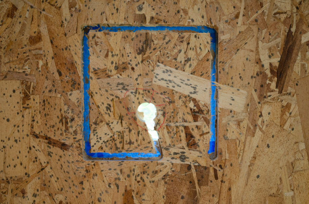
Start router in the pilot hole, drag it to the edge, then trace the perimeter of the first frame. Shown here, a moment before completing the cut. This one went perfectly. I am pleased with my temporary frame technique.
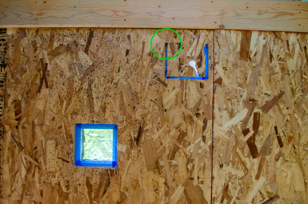
I had a feeling the second light port wasn’t going to be that easy. Indeed, the base of the router (green circle) hit this bit of lumber which prevented the completion of full perimeter. Oh oh. Now what?
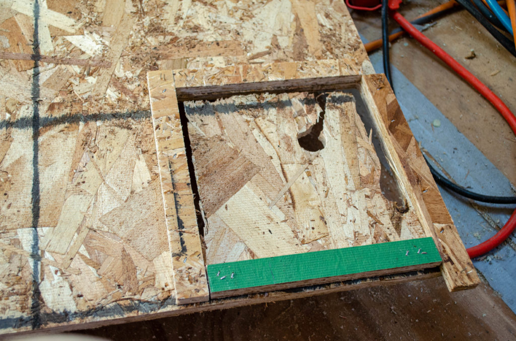
I took the board down, along with the temporary frames. I then used the edges of what was cut to locate the frame, which I stapled to the back of the board, rather than the wall. I knew the hole was in the right place because the three edges I could get were aligned with the frame when the frame was on the wall, around the window. Now the frame is aligned with the hole and I use the pre-cut frame piece (green side showing) to span the unfinished side.
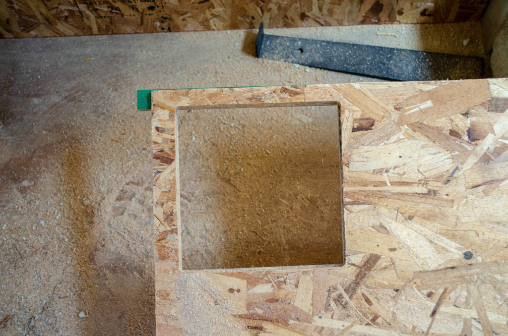
Turn the board over, run the router to trace the frame (stapled to the back of the board– you can see the green side of one of the pieces sticking out). Presto! A perfect window hole, close to the edge. Remove the frame.
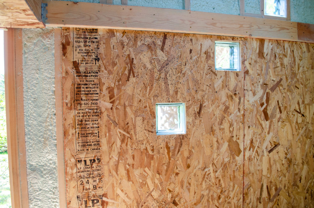
Install the board for real. Perfection! The two light ports shine through nicely, perfectly accommodated. The upper light ports will be done the same way. Two of them are close to hard edges, so there will be some frame games for those, as well.